没有合适的资源?快使用搜索试试~ 我知道了~
SI4463无线模块编程指导
5星 · 超过95%的资源 需积分: 49 232 下载量 119 浏览量
2013-10-18
20:02:11
上传
评论 3
收藏 620KB PDF 举报
温馨提示
试读
48页
此文档时英文的文档,详细的解释了SI4463官方例程包的编写思路和流程。适合想要开发SI4463模块的研发人员作为参考。
资源推荐
资源详情
资源评论
Rev. 0.1 2/12 Copyright © 2011 by Silicon Laboratories AN633
AN633
Si446X PROGRAMMING GUIDE AND SAMPLE CODES
1. Introduction
This document provides an overview of configuring the Si446x for transmitter, receiver, and transceiver operation
using simple software example codes.
The following examples are covered in this programming guide:
How to transmit a packet in simple Packet Handler mode (Sample Code 1)
How to receive a packet in simple Packet Handler mode (Sample Code 1)
How to transmit a packet in Packet Handler mode using a FIELD (Sample Code 2)
How to receive a packet in Packet Handler mode using a FIELD (Sample Code 2)
How to implement bidirectional packet-based communication (Sample Code 3)
How to use variable packet length (Sample Code 3)
How to use 4(G)FSK modulation (Sample Code 4)
Please contact the Wireless Support Team for the latest example source codes.
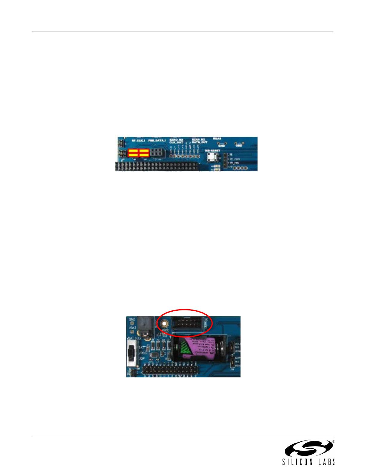
2. Hardware Options
The source code is provided for the Si4460-B0, Si4461-B0, Si4463-B0, and Si4464-B0 devices.
A separate Silicon Labs IDE* workspace is provided for each example on the UDP platform.
*Note: Use IDE 4.40 or higher.
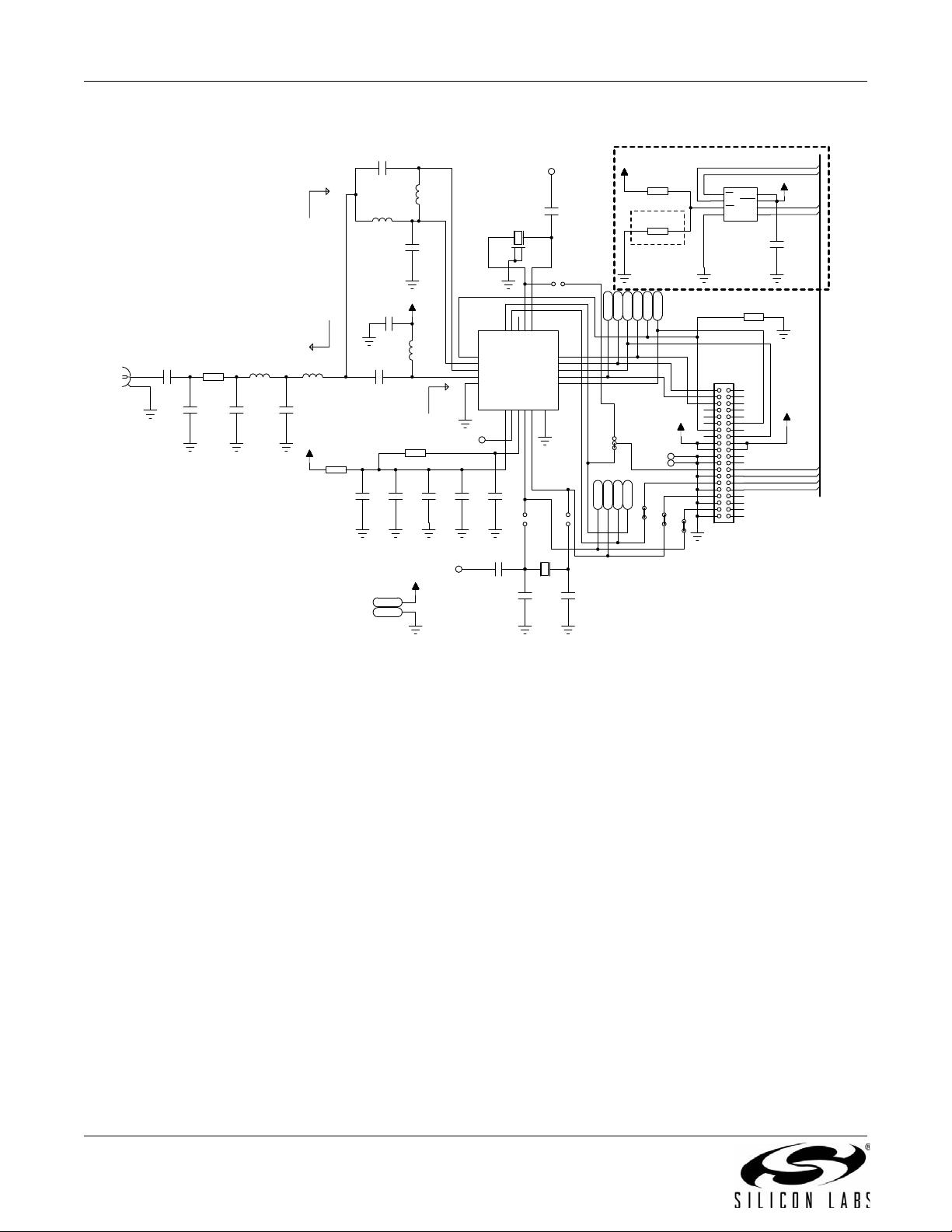
2.1. Test Card Options
The power amplifier and the LNA are not connected together inside the Si446x devices. Several different test cards
are introduced to provide examples for main connection schemes.
On test cards using direct-tie connection, the TX and RX pins are directly connected externally, eliminating the
need for an RF switch.
On test cards using an RF switch, separate transmit and receive pins on the RFIC are connected to an antenna via
an SPDT RF switch for single antenna operation. The radio device assists with control of the RF switch. By routing
the RX State and TX State signals to any two GPIOs, the radio can automatically control the RF switch. The GPIOs
will disable the RF switch if the radio is not in active mode.
On test cards using split connection, the TX and RX pins are routed to different antenna connectors.
Test cards with external PA (FEM or FET type) are also provided by Silabs.
AN633
2 Rev. 0.1
Figure 1. Direct Tie Si4461 Test Card Schematic
The example source code can be compiled for various test cards and radios. The following compiling option
(located at the beginning of the ezrp_next_api.h file) selects the proper configuration (#define
EZRP_NEXT_TestCard TestCard_4463_TCE20C915). The selection has to be made based on the marketing
number of the test card.
TestCard_4463_TSQ20D169
TestCard_4463_TSQ27F169
TestCard_4461_TCE14D434
TestCard_4460_TCE10D434
TestCard_4463_TCE20B460
TestCard_4463_TCE20C460
TestCard_4460_TSC10D868
TestCard_4460_TCE10D868
TestCard_4461_TSC14D868
TestCard_4461_TCE16D868
TestCard_4463_TCE20B868
TestCard_4463_TCE20C868
TestCard_4463_TCE27F868
TestCard_4463_TCE20B915
TestCard_4463_TCE20C915
%RDUG,GHQWLILFDWLRQ((3520
:ULWHSURWHFW5 N
2SWLRQDOSDUW
LV12702817('
2KPORDG
6LB%6Z&XUU'LUHFW7LHPDWFKLQJIRU0+]
aMRKPV5;
a.MRKPV7;
aRKPVS)
3RXW G%P2% [''$& [
aMRKPV
&
S)
&
S)
&
Q)
&
X)
&
Q)
5
N
5
N
5
1)
&
1)
6-
6-
6-
6-
&6
&215
&6
62
:3
*1'
6,
6&.
+2/'
9&&
8
$$&
4
N+]
7=$
*1'
73
;287
6'1
5;3
5;1
7;
1&
9%$7$
7;5$03
9%$7'
*3,2B
*3,2B
1,54
6&/.
6'2
6',
16(/
;287
;,1
*1';
*3,2B
*3,2B
(3
(3
8
6,
7;5$03
4
0+]
7=$
6-
6-
6-
&
1)
-$
-%
/)
5
&0
S)
&0
S)
&5
S)
&5
S)
&
S)
/&
Q+
/0
Q+
/5
Q+
75;
60$5$
&&
S)
/0
Q+
/5
Q+
&
S)
/0
5
&
S)
&
S)
&
Q)
&0
1)
5
5
9
9
(%,'B16(/
(%,'B6&.
(%,'B026,
9
(%,'B026,
(%,'B0,62
(%,'B6&.
(%,'B16(/
(%,'B0,62
9''
6&/.
6',
6'2
16(/
6'1
1,54
*3,2
*3,2
*3,2
*3,2
9''
9''
9''
5;1
5;3
7;
*1'
AN633
Rev. 0.1 3
TestCard_4463_TCE30E915
TestCard_4464_TCE20B420
Note: The transmit output of Si446x devices must be terminated properly before output power is enabled. This is accomplished
by using a proper antenna or connecting the power amplifier to an RF instrument that provides 50 termination to
ensure proper operation and protect the device from damage.
2.2. UDP Platform
The example source codes run on the Universal Development Platform (UDP). The UDP consists of several
boards. Both the MCU card and the test card are plugged into the UDP Motherboard (UP-BACKPLANE-01EK). It
provides power supply and USB connectivity for the development system. The MCU card (UPMP-F960-EMIF-EK)
has several peripherals for simple software development (e.g. LEDs, Push Buttons, etc.), and it has a socket for
various MCU selections. UPPI-F960-EK MCU Pico board is used for software development, which has a
Si8051F960 MCU on it. It controls the radio on the test card using the SPI bus. The test card is connected to the
40-pin connector (J3) on the UDP Motherboard where the following signals are used (UDP_MB refers to UDP
Motherboard, MCU refers to the MCU of the UPMP-F960-EMIF card):
For more info on the UDP platform, refer to the “UDP Motherboard User's Guide”.
Table 1. Si446x Pin Assignments
Si446x UDP Platform
Pin Number Pin Name Pin Function Pin Name
Exposed pad, 18 GND Ground Ground
6, 8 VDD Supply input PWR_RADIO through UDP_MB –J21
11 NIRQ Interrupt output, active low MCU / P1.6
1 SDN Shutdown input, active high MCU / P1.7
15 NSEL SPI select input MCU / P2.3
12 SCLK SPI clock input MCU / P2.0
14 SDI SPI data input MCU / P2.2
13 SDO SPI data output MCU / P2.1
AN633
4 Rev. 0.1
2.2.1. Setting up the Development Board
Before downloading example code into the MCU, the UDP platform must be configured according to the following
instructions:
1. Connect the Si446x test card to the 40-pin (J3) connector.
2. Connect the antenna(s) to the SMA connector(s) of the test card.
3. Set S5 to OFF to disable the 6.5 V voltage on pin 36 of the test card connector.
4. Set SW5 to UDP on the MCU card.
5. Set SW7 and SW12 to VBAT on the MCU card.
6. Short JP19 and JP21 jumpers as shown in Figure 2 to provide VDD for the radio (the current consumption
of the radio can be measured through these jumpers).
Figure 2. Jumper Positions (JP19, JP21)
2.2.2. Downloading and Running the Example Codes
1. Connect the USB debug adapter to the 10-pin J13 connector of the MCU card.
2. To power the board, connect a 9 V dc power supply to J20 (UDP_MB), or connect the development board
to a PC over USB cable (J16 on UDP_MB).
3. Turn on S3 on UDP_MB (Power switch).
4. Start Silicon Labs IDE on your computer.
5. Connect the IDE to the C8051F960 MCU of the development board by pressing the Connect button on the
toolbar or by invoking the menu Debug Connect menu item.
6. Erase the FLASH of the C8051F960 MCU in the Debug Download object code Erase all code space
menu item.
7. Download the desired example HEX file either by hitting the Download code (Alt+D) toolbar button or from
the Debug Download object code menu item.
8. Hit the Disconnect toolbar button or invoke the Debug Disconnect menu item to release the device from
halt and let it run.
Figure 3. J13 Connector on the MCU Card
AN633
Rev. 0.1 5
2.3. Using the Resources of the Development Board
The example programs are written in “C”. General headers and code files are provided to ease the programming of
the development board.
The file called compiler_defs.h contains macro definitions to accommodate 8051 compiler differences and
declaring special function registers and other 8051-specific features. Using these macros allows the example code
to be compiled with several common C compilers, such as Keil, SDCC, Raisonance, etc.
2.3.1. Initialization
The file called C8051F960_defs.h contains the register/bit definitions for the C8051F96x MCU family.
The file called hardware_defs.h contains the UDP platform-specific definitions.
The following macros in the hardware_defs.h file assign a label to the given IO port, so they can be more easily
referenced in the source code. For example, the SBIT(EZRP_PWRDN, SFR_P1, 7); line assigns the
EZRP_PWRDN label to P1.7 (refer to Table 1), which the SDN pin of the radio is connected to:
The void MCU_Init(void) function in the main.c file initializes all the peripherals necessary for the example
programs.
UDP platform provides an own SPI interface for the test card connected to J3 connector, other SPI devices should
not conflict with the test card. SPI interface connected to the radio test card are referred as SPI “0” in the sample
codes.
2.3.2. LED and Push Buttons
The LED control and push button reading functions can be found in the control_IO.c file:
void SetLed(U8 number)
void ClearLed(U8 number)
bit GetPB(U8 number)
Reading the push buttons is not trivial, as a button and an LED share the same pin of the MCU. During the short
period of reading a push button, the pin is set high and its direction is changed to input. This change may cause a
brief but unnoticeable LED state change. After the push button is checked, the original LED status is restored.
SBIT(MCU_SDA, SFR_P0, 6);
SBIT(MCU_SCL, SFR_P0, 7);
SBIT(MCU_SCK, SFR_P2, 0);
SBIT(MCU_MISO,SFR_P2, 1);
SBIT(MCU_MOSI,SFR_P2, 2);
SBIT(MCU_NSEL, SFR_P2, 3);
SBIT(EZRP_NIRQ, SFR_P1, 6);
SBIT(EZRP_PWRDN, SFR_P1, 7);
SBIT(PB1, SFR_P3, 0);
SBIT(PB2, SFR_P3, 1);
SBIT(PB3, SFR_P3, 2);
SBIT(PB4, SFR_P3, 3);
SBIT(LED1, SFR_P3, 0);
SBIT(LED2, SFR_P3, 1);
SBIT(LED3, SFR_P3, 2);
SBIT(LED4, SFR_P3, 3);
剩余47页未读,继续阅读
liu_hong_liang
- 粉丝: 1
- 资源: 6
上传资源 快速赚钱
- 我的内容管理 展开
- 我的资源 快来上传第一个资源
- 我的收益 登录查看自己的收益
- 我的积分 登录查看自己的积分
- 我的C币 登录后查看C币余额
- 我的收藏
- 我的下载
- 下载帮助
最新资源
- 全卷积网络基于voc2012数据集简单pytorch实现
- pycharm的一些介绍-用于更好的学习python
- 基于C++的程序设计大赛天梯赛L2答案(天梯赛)
- 基于python实现的三次样条插值和均值插值法实现
- Python语言教程2-python批量图片大小处理-多文件夹
- Python语言教程1-python批量图片重命名,将后缀某几个不想要的字去除
- Space Combat Kit 太空战斗套件Unity游戏开发插件资源unitypackage C#
- Universal Device Preview 通用设备预览Unity游戏开发插件资源unitypackage
- Paladin Anim Set 圣骑士动画集Unity游戏动作动画插件资源unitypackage
- 计算机财务管理期末考报表部分题目及答案.doc
资源上传下载、课程学习等过程中有任何疑问或建议,欢迎提出宝贵意见哦~我们会及时处理!
点击此处反馈
安全验证
文档复制为VIP权益,开通VIP直接复制
信息提交成功
- 1
- 2
- 3
- 4
- 5
- 6
前往页