拉扎维模拟CMOS集成电路第二版最新答案-含目录
需积分: 5 29 浏览量
2023-02-28
15:22:35
上传
评论 4
收藏 67.56MB PDF 举报

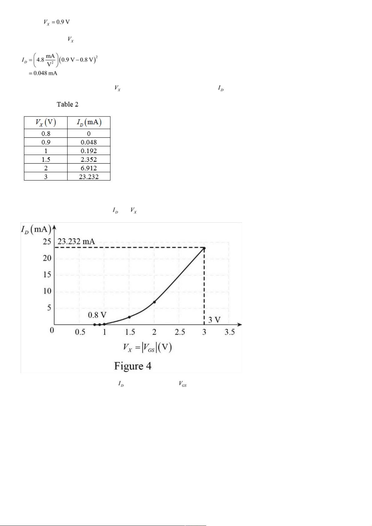
Design of Analog CMOS Integrated Circuits
Solution for Chapter 2 Problem 1P
Question:
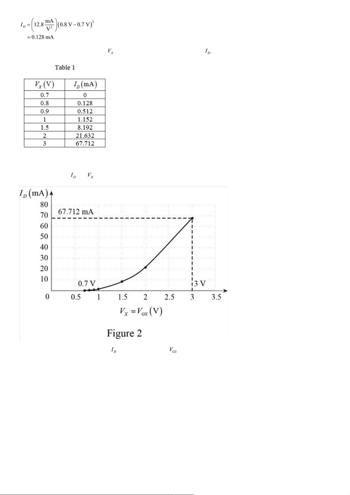
For W/L = 50/0.5, plot the drain current of an NFET and a PFET as a function of |V
GS
| as |V
GS
| varies from
0 to 3 V. Assume that |V
DS
| = 3 V.
Step 1 Of 9
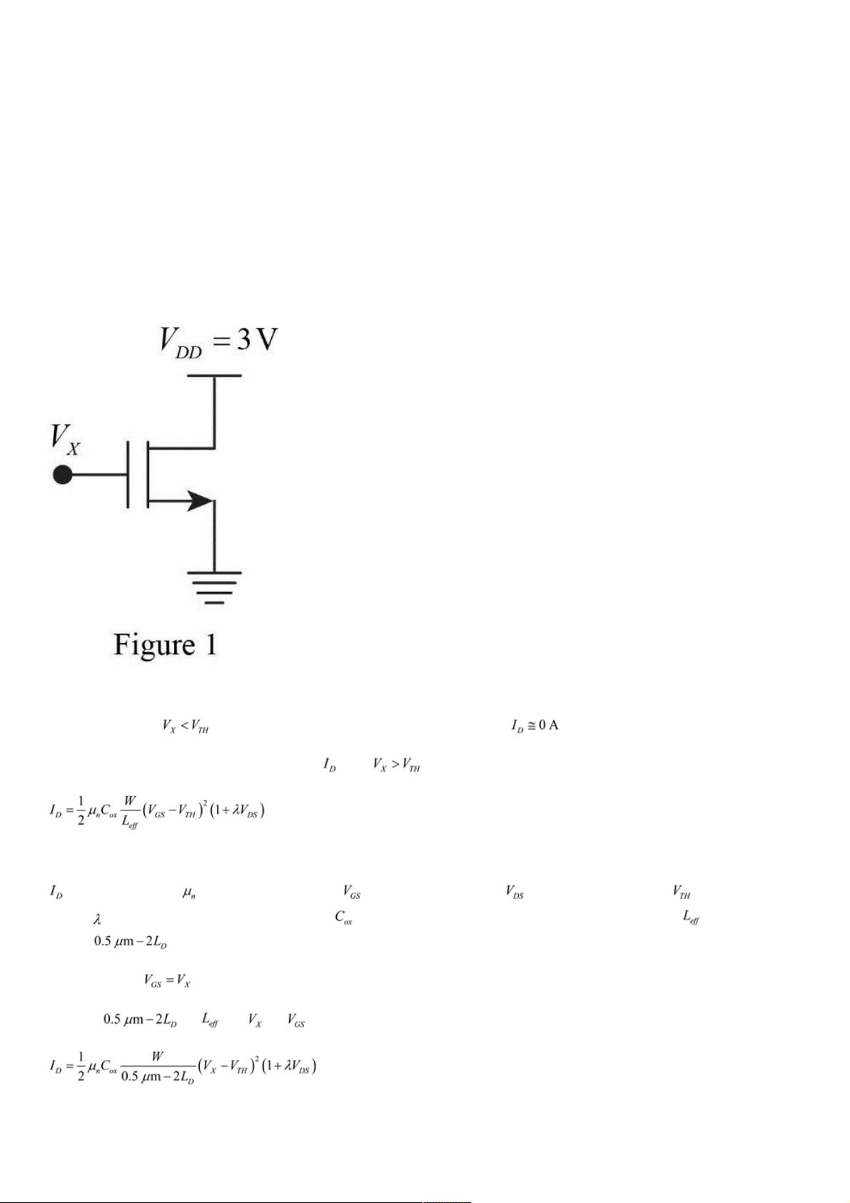
For NFET:
The schematic diagram of NFET is drawn as shown in Figure 1.
Step 2 Of 9
Refer to Figure 1, for the device is in off condition. Therefore, the drain current .
Consider the general expression for the drain current when .
…… (1)
Here,
is the drain current is, is the mobility of electrons, is the gate-source voltage, is the drain-source voltage, is the threshold
voltage, is the channel-length modulation coefficient, is the gate oxide capacitance per unit area, W is the width, and is the length,
which is .
Refer to Figure 1, .
Substitute for and for in equation (1).
…… (2)
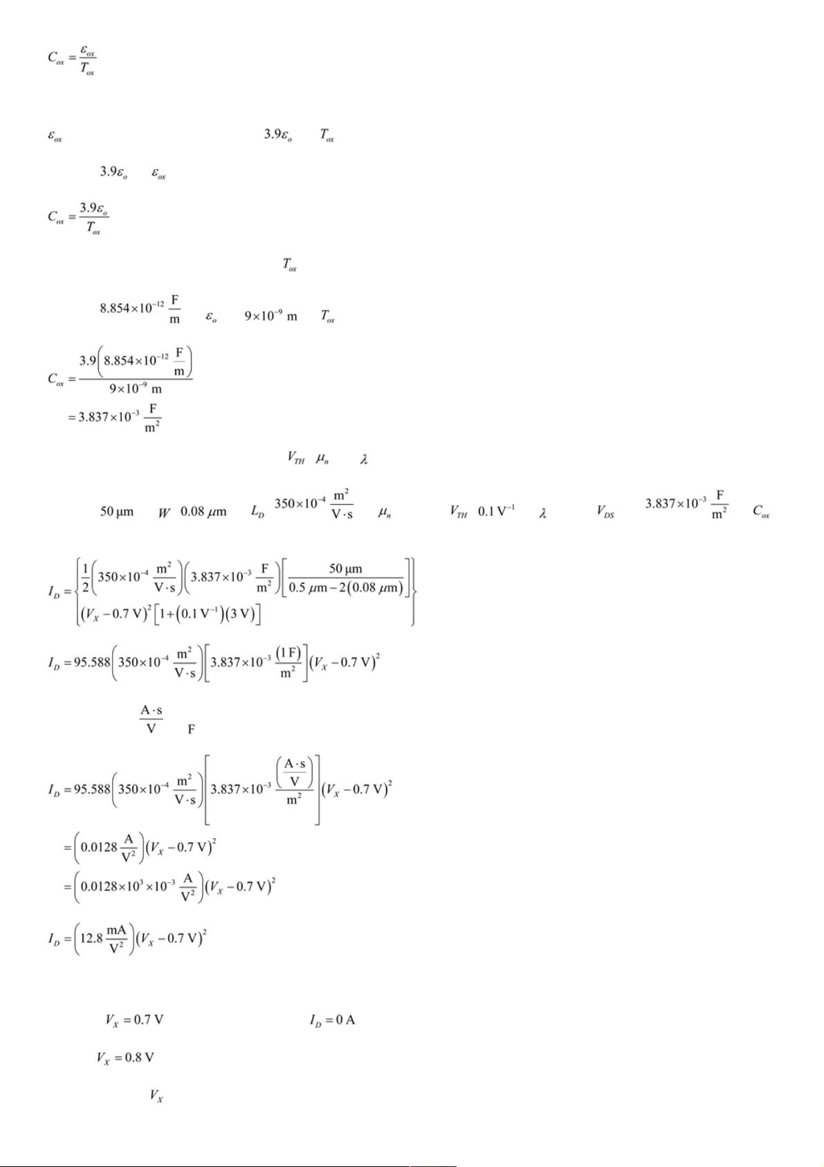
Step 3 Of 9
Consider the expression for the gate oxide capacitance per unit area.
剩余1602页未读,继续阅读
资源评论


