


Philips Semiconductors
I
2
S bus specification
1
February 1986 Revised: June 5, 1996
1.0 INTRODUCTION
Many digital audio systems are being introduced into the consumer
audio market, including compact disc, digital audio tape, digital
sound processors, and digital TV-sound. The digital audio signals in
these systems are being processed by a number of (V)LSI ICs,
such as:
•A/D and D/A converters;
•digital signal processors;
•error correction for compact disc and digital recording;
•digital filters;
• digital input/output interfaces.
Standardized communication structures are vital for both the
equipment and the IC manufacturer, because they increase system
flexibility. To this end, we have developed the inter-IC sound (I
2
S)
bus – a serial link especially for digital audio.
2.0 BASIC SERIAL BUS REQUIREMENTS
The bus has only to handle audio data, while the other signals, such
as sub-coding and control, are transferred separately. To minimize
the number of pins required and to keep wiring simple, a 3-line serial
bus is used consisting of a line for two time-multiplexed data
channels, a word select line and a clock line.
Since the transmitter and receiver have the same clock signal for
data transmission, the transmitter as the master, has to generate the
bit clock, word-select signal and data. In complex systems however,
there may be several transmitters and receivers, which makes it
difficult to define the master. In such systems, there is usually a
system master controlling digital audio data-flow between the
various ICs. Transmitters then, have to generate data under the
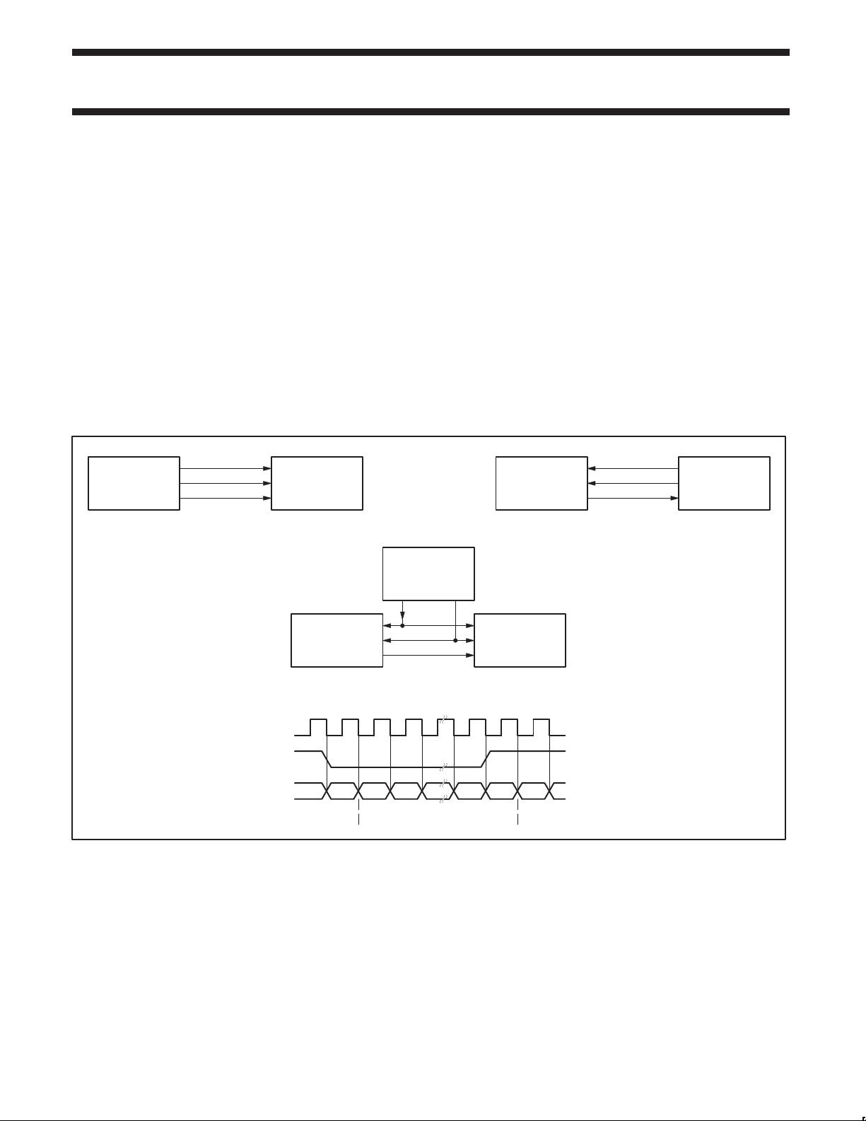
control of an external clock, and so act as a slave. Figure 1
illustrates some simple system configurations and the basic
interface timing. Note that the system master can be combined with
a transmitter or receiver, and it may be enabled or disabled under
software control or by pin programming.
TRANSMITTER
clock SCK
word select WS
data SD
RECEIVER
TRANSMITTER = MASTER
TRANSMITTER
SCK
WS
SD
RECEIVER
RECEIVER = MASTER
TRANSMITTER
SCK
WS
SD
RECEIVER
CONTROLLER = MASTER
CONTROLLER
SCK
WS
SD
WORD n–1
RIGHT CHANNEL
WORD n+1
RIGHT CHANNEL
WORD n
LEFT CHANNEL
LSB MSBMSB
SN00119
Figure 1. Simple System Configurations and Basic Interface Timing


评论22
最新资源