


1
Motorola Optoelectronics Device Data
!
(400 Volts Peak)
The MOC3041, MOC3042 and MOC3043 devices consist of gallium arsenide
infrared emitting diodes optically coupled to a monolithic silicon detector
performing the function of a Zero Voltage Crossing bilateral triac driver.
They are designed for use with a triac in the interface of logic systems to
equipment powered from 115 Vac lines, such as solid–state relays, industrial
controls, motors, solenoids and consumer appliances, etc.
• Simplifies Logic Control of 115 Vac Power
• Zero Voltage Crossing
• dv/dt of 2000 V/µs Typical, 1000 V/µs Guaranteed
•
To order devices that are tested and marked per VDE 0884 requirements, the
suffix ”V” must be included at end of part number. VDE 0884 is a test option.
Recommended for 115/240 Vac(rms) Applications:
• Solenoid/Valve Controls
• Temperature Controls
• Lighting Controls • E.M. Contactors
• Static Power Switches
• AC Motor Starters
• AC Motor Drives • Solid State Relays
MAXIMUM RATINGS
(T
A
= 25°C unless otherwise noted)
Rating
Symbol Value Unit
INFRARED EMITTING DIODE
Reverse Voltage V
R
6 Volts
Forward Current — Continuous I
F
60 mA
Total Power Dissipation @ T
A
= 25°C
Negligible Power in Output Driver
Derate above 25°C
P
D
120
1.41
mW
mW/°C
OUTPUT DRIVER
Off–State Output Terminal Voltage V
DRM
400 Volts
Peak Repetitive Surge Current
(PW = 100 µs, 120 pps)
I
TSM
1 A
Total Power Dissipation @ T
A
= 25°C
Derate above 25°C
P
D
150
1.76
mW
mW/°C
TOTAL DEVICE
Isolation Surge Voltage
(1)
(Peak ac Voltage, 60 Hz, 1 Second Duration)
V
ISO
7500 Vac(pk)
Total Power Dissipation @ T
A
= 25°C
Derate above 25°C
P
D
250
2.94
mW
mW/°C
Junction Temperature Range T
J
–40 to +100 °C
Ambient Operating Temperature Range
(2)
T
A
–40 to +85 °C
Storage Temperature Range
(2)
T
stg
–40 to +150 °C
Soldering Temperature (10 s) T
L
260 °C
1. Isolation surge voltage, V
ISO
, is an internal device dielectric breakdown rating.
1. For this test, Pins 1 and 2 are common, and Pins 4, 5 and 6 are common.
2. Refer to Quality and Reliability Section in Opto Data Book for information on test conditions.
Preferred devices are Motorola recommended choices for future use and best overall value.
GlobalOptoisolator is a trademark of Motorola, Inc.
Order this document
by MOC3041/D
SEMICONDUCTOR TECHNICAL DATA
GlobalOptoisolator
Motorola, Inc. 1995
*Motorola Preferred Device
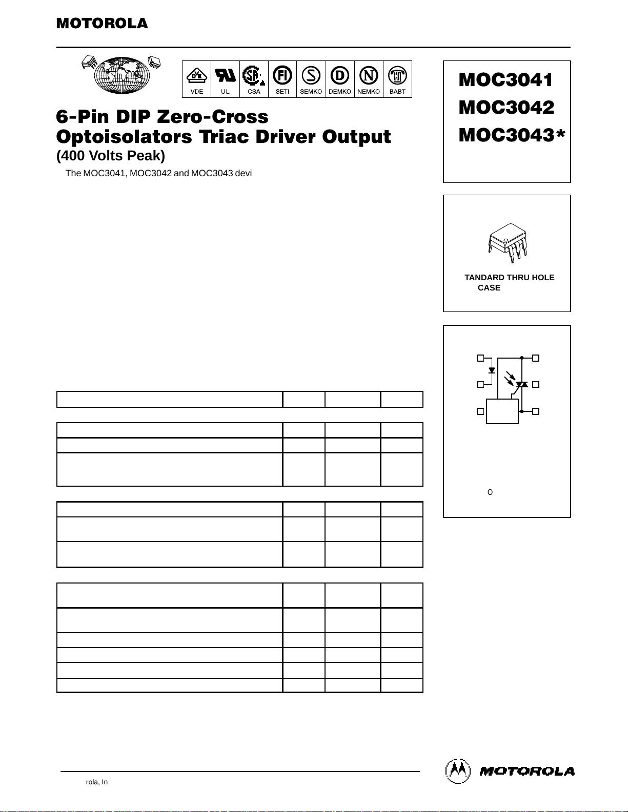
COUPLER SCHEMATIC
[IFT = 15 mA Max]
STANDARD THRU HOLE
CASE 730A–04
[IFT = 10 mA Max]
[IFT = 5 mA Max]
1. ANODE
2. CATHODE
3. NC
4. MAIN TERMINAL
5. SUBSTRATE
5. DO NOT CONNECT
6. MAIN TERMINAL
1
2
3
6
5
4
ZERO
CROSSING
CIRCUIT
6
1
STYLE 6 PLASTIC
(Replaces MOC3040/D)
元器件交易网www.cecb2b.com


评论0