没有合适的资源?快使用搜索试试~ 我知道了~
KEB P6是风力发电机组变桨系统的伺服驱动器,用于风力发电机组变桨控制,是现有的集成度最高的变桨专用伺服驱动器,性能好可靠性高。
资源推荐
资源详情
资源评论
COMBIVERT
GB Instruction Manual Pitch Inverter P6
Rated Current 45 A/52A
Mat.No. Rev.
00P6NEB-0000 1B
P6
GB - 3
Table of Contents
1. Introduction ......................................................................................................5
1.1 Preface .................................................................................................................................. 5
1.2 Validity and liability ............................................................................................................. 5
1.3 Copyright .............................................................................................................................. 6
1.4 Speciedapplication ........................................................................................................... 6
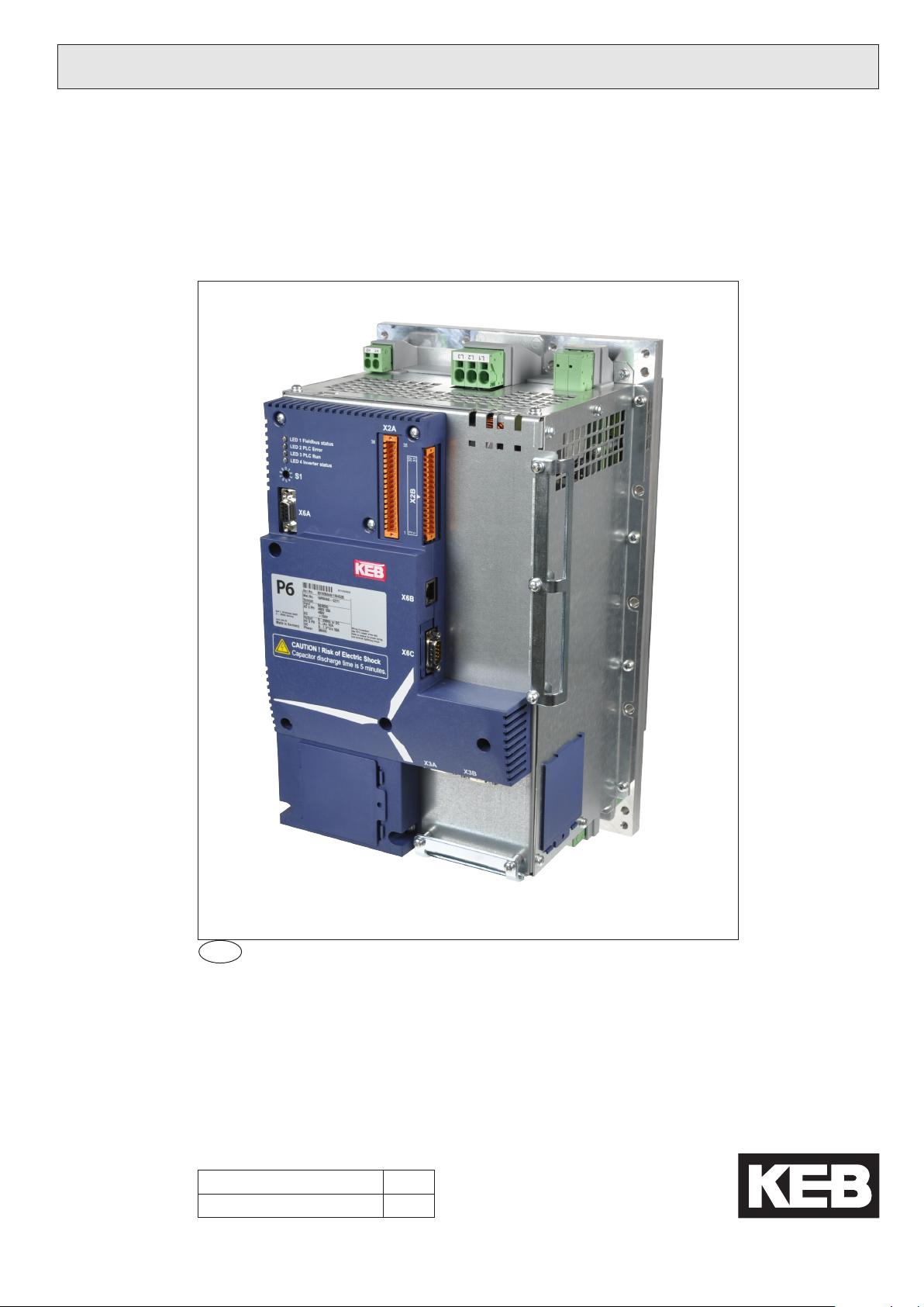
1.5 Product description ............................................................................................................. 6
1.6 Options ................................................................................................................................. 7
1.7 Unitidentication ................................................................................................................ 7
2. Safety Instructions ..........................................................................................8
2.1 General instructions ............................................................................................................ 8
2.2 Transport, storage and installation .................................................................................... 8
2.3 Electrical connection ........................................................................................................... 9
2.4 EMC Instructions ............................................................................................................... 12
2.5 EMC conform installation ................................................................................................. 12
3. Technical Data ...............................................................................................13
3.1 Overload (OL) function ...................................................................................................... 14
3.2 Operating conditions ......................................................................................................... 14
3.3 Dimensions and Weights .................................................................................................. 16
3.3.1 Mounting cutout ................................................................................................................... 17
4. Hardware ........................................................................................................18
4.1 Device overview ................................................................................................................. 18
4.1.1 Terminals ............................................................................................................................. 19
4.1.1.1 Connecting wires to X1A and X1B ....................................................................................... 19
4.1.1.2 Connecting wires to X2A and X2B ....................................................................................... 19
4.2 Power part .......................................................................................................................... 20
4.2.1 Description of the terminal blocks ........................................................................................ 20
4.2.1.1 Terminal block X1A .............................................................................................................. 20
4.2.1.2 Terminal block X1B .............................................................................................................. 20
4.2.2 Mains connection ................................................................................................................. 21
4.2.3 Motor connection ................................................................................................................. 21
4.2.3.1 AC motor connection ........................................................................................................... 21
4.2.3.2 DC motor connection (option) .............................................................................................. 21
4.2.3.3 Motor temperature detection, terminals T1, T2 .................................................................... 22
4.2.4 Brake control ........................................................................................................................ 22
4.2.4.1 Control of a 24 Vdc brake..................................................................................................... 22
4.2.4.2 Control of a 150…300 Vdc brake ......................................................................................... 22
4.2.5 Connection of the batteries/ultracaps .................................................................................. 23
4.2.6 Connection of an external braking resistor .......................................................................... 23
4.2.7 Connection of the internal heating ....................................................................................... 23
4.3 Control part ........................................................................................................................ 24
4.3.1 Description of the terminals and controls ............................................................................. 24
4.3.2 LED‘s for program run and error display .............................................................................. 25
4.3.3 Address selector switch S1 .................................................................................................. 25
4.3.4 Real-time clock .................................................................................................................... 25
GB - 4
Table of Contents
4.3.5 Control terminal block X2A .................................................................................................. 26
4.3.5.1 External supply .................................................................................................................... 26
4.3.5.2 Digital outputs ...................................................................................................................... 27
4.3.5.3 Temperature inputs .............................................................................................................. 27
4.3.5.4 Analog inputs ....................................................................................................................... 27
4.3.5.5 Relay output ......................................................................................................................... 28
4.3.6 Control terminal block X2B .................................................................................................. 28
4.3.6.1 Digital inputs ........................................................................................................................ 28
4.3.7 Encoder interfaces ............................................................................................................... 29
4.3.7.1 Pin assignment encoder channel 1 (X3A) ........................................................................... 29
4.3.7.2 Pin assignment encoder channel 2 (X3B) ........................................................................... 30
4.3.7.3 Encoder cable ...................................................................................................................... 30
4.3.8 Diagnostic interface X6A ...................................................................................................... 31
4.3.9 Ethernet interface (X6B) ...................................................................................................... 31
4.3.10 Fieldbus interface X6C ........................................................................................................ 32
Annex A .....................................................................................................................33
A.1 Overload protection in the lower speed range ............................................................... 33
A.2 Potential separation .......................................................................................................... 34
A.3 Supply of the digital inputs and outputs ......................................................................... 35
A.4 Maintenance ....................................................................................................................... 35
A.5 Storage ............................................................................................................................... 36
Annex B .....................................................................................................................37
B.1 Certication ........................................................................................................................ 37
B.1.1 CE Marking .......................................................................................................................... 37
B.1.2 UL Marking........................................................................................................................... 37
GB - 5
Preface
1. Introduction
1.1 Preface
First we would like to welcome you as a customer of the company Karl E. Brinkmann GmbH
and congratulation to the purchase of this product. You have decided for a product on highest
technical level.
The described hard- and software are developments of the Karl E. Brinkmann GmbH. The
enclosed documents correspond to conditions valid at printing. Misprint, mistakes and tech-
nical changes reserved.
The instruction manual must be made available to the user. Prior to performing any work on
the unit the user must familiarize himself with the unit. This especially applies to the know-
ledge and observance of the following safety and warning indications. The pictographs used
in this instruction manual have following meaning:
Danger
Is used, if life or health of the user are endangered or subs-
tantial damage to property can occur.
Warning
Caution
Attention
Is used, if a measure is necessary for safe and trouble-free
operation.
observe at
all costs
Information
Is used, if a measure simplies the handling or operation of
the unit.
Aid
Tip
Non-observance of the safety instructions leads to the loss of any liability claims. This list is
not exhaustive.
1.2 Validity and liability
The use of our units in the target products is outside of our control and therefore lies
exclusively in the area of responsibility of the machine manufacturer.
The information contained in the technical documentation, as well as any user-specic advice
in spoken and written and through tests, are made to best of our knowledge and information
about the application. However, they are considered for information only without responsibili-
ty. This also applies to any violation of industrial property rights of a third-party.
Selection of our units in view of their suitability for the intended use must be done generally
by the user.
Tests can only be done within the application by the machine manufacturer. They must be
repeated, even if only parts of hardware, software or the unit adjustment are modied.
Unauthorised opening and tampering may lead to bodily injury and property damage and
may entail the loss of warranty rights. Original spare parts and authorized accessories by the
manufacturer serve as security. The use of other parts excludes liability for the consequences
arising out of.
The suspension of liability is especially valid also for operation interruption loss, loss of prot,
data loss or other damages. This is also valid, if we referred rst to the possibility of such
damages.
If single regulations should be or become void, invalid or impracticable, the effectivity of all
other regulations or agreements is not affected.
剩余39页未读,继续阅读
资源评论
harrycao520
- 粉丝: 0
- 资源: 1
上传资源 快速赚钱
- 我的内容管理 展开
- 我的资源 快来上传第一个资源
- 我的收益 登录查看自己的收益
- 我的积分 登录查看自己的积分
- 我的C币 登录后查看C币余额
- 我的收藏
- 我的下载
- 下载帮助
安全验证
文档复制为VIP权益,开通VIP直接复制
信息提交成功