


January 2010 Doc ID 14220 Rev 4 1/48
UM0488
User manual
STM3210E-EVAL
evaluation board
Introduction
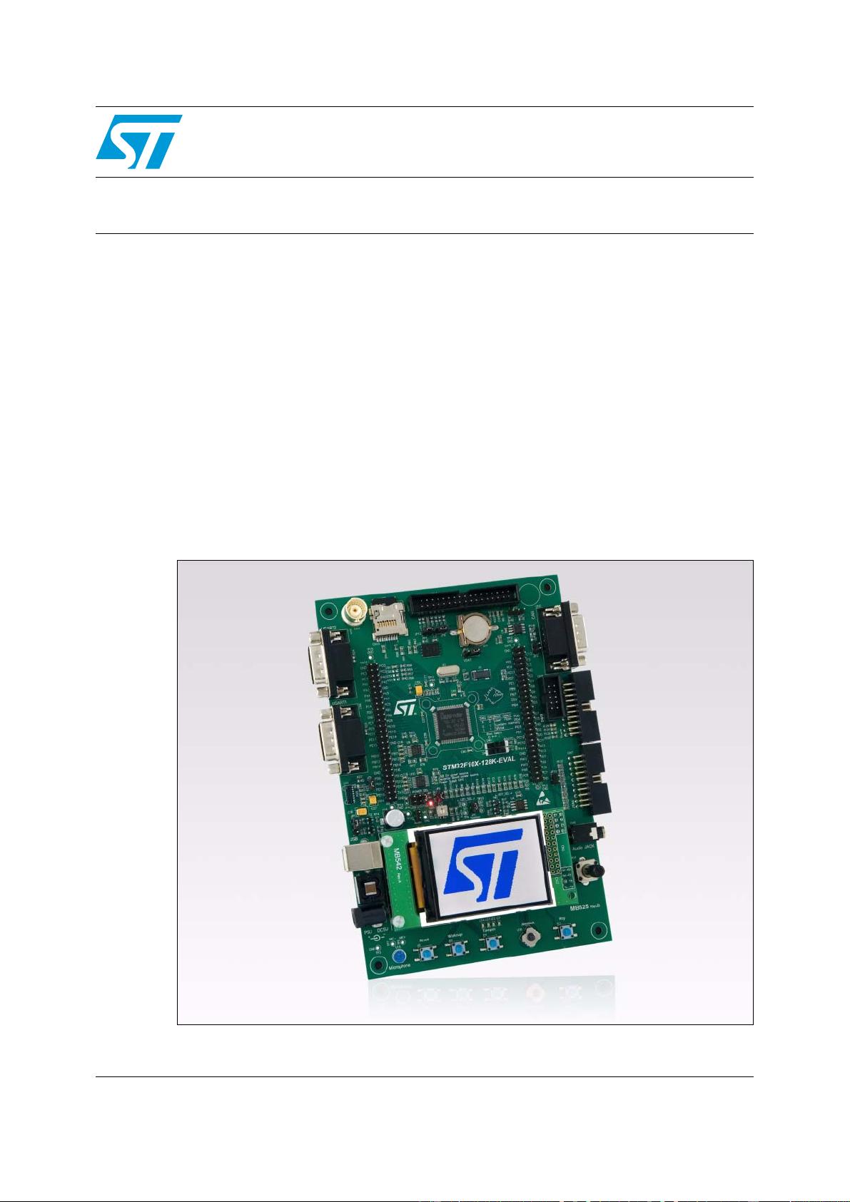
The STM3210E-EVAL evaluation board is designed as a complete development platform for
STMicroelectronic's ARM Cortex-M3 core-based STM32F103Z microcontroller with full
speed USB2.0, CAN2.0A/B compliant interface, two I
2
S channels, two I
2
C channels, five
USART channels with smartcard support, three SPI channels, two DAC channels, FSMC
interface, SDIO, internal 64 KB SRAM and 512 KB Flash, JTAG and SWD debug support.
The full range of hardware features on the board helps you to evaluate all peripherals (USB,
motor control, CAN, MicroSD card, smartcard, USART, NOR Flash, NAND flash, SRAM)
and develop your own applications. Extension headers make it possible to easily connect a
daughter board or wrapping board for your specific application.
Figure 1. STM3210E-EVAL evaluation board
Order code
To order the STM32F103Z evaluation board, use the order code STM3210E-EVAL.
www.st.com
Contents UM0488
2/48 Doc ID 14220 Rev 4
Contents
1 Overview . . . . . . . . . . . . . . . . . . . . . . . . . . . . . . . . . . . . . . . . . . . . . . . . . . 4
1.1 Features . . . . . . . . . . . . . . . . . . . . . . . . . . . . . . . . . . . . . . . . . . . . . . . . . . . 4
1.2 Demonstration software . . . . . . . . . . . . . . . . . . . . . . . . . . . . . . . . . . . . . . . 4
2 Hardware layout and configuration . . . . . . . . . . . . . . . . . . . . . . . . . . . . . 5
2.1 Power supply . . . . . . . . . . . . . . . . . . . . . . . . . . . . . . . . . . . . . . . . . . . . . . . 7
2.2 Boot option . . . . . . . . . . . . . . . . . . . . . . . . . . . . . . . . . . . . . . . . . . . . . . . . . 8
2.3 Clock source . . . . . . . . . . . . . . . . . . . . . . . . . . . . . . . . . . . . . . . . . . . . . . . . 8
2.4 Reset source . . . . . . . . . . . . . . . . . . . . . . . . . . . . . . . . . . . . . . . . . . . . . . . 8
2.5 Audio . . . . . . . . . . . . . . . . . . . . . . . . . . . . . . . . . . . . . . . . . . . . . . . . . . . . . 9
2.6 Serial Flash . . . . . . . . . . . . . . . . . . . . . . . . . . . . . . . . . . . . . . . . . . . . . . . . 9
2.7 CAN . . . . . . . . . . . . . . . . . . . . . . . . . . . . . . . . . . . . . . . . . . . . . . . . . . . . . . 9
2.8 RS232 connectors . . . . . . . . . . . . . . . . . . . . . . . . . . . . . . . . . . . . . . . . . . 10
2.9 Motor control . . . . . . . . . . . . . . . . . . . . . . . . . . . . . . . . . . . . . . . . . . . . . . 10
2.10 Smartcard . . . . . . . . . . . . . . . . . . . . . . . . . . . . . . . . . . . . . . . . . . . . . . . . . 11
2.11 MicroSD card . . . . . . . . . . . . . . . . . . . . . . . . . . . . . . . . . . . . . . . . . . . . . . 11
2.12 Temperature sensor . . . . . . . . . . . . . . . . . . . . . . . . . . . . . . . . . . . . . . . . . 12
2.13 Analog input . . . . . . . . . . . . . . . . . . . . . . . . . . . . . . . . . . . . . . . . . . . . . . . 12
2.14 IrDA . . . . . . . . . . . . . . . . . . . . . . . . . . . . . . . . . . . . . . . . . . . . . . . . . . . . . 12
2.15 USB . . . . . . . . . . . . . . . . . . . . . . . . . . . . . . . . . . . . . . . . . . . . . . . . . . . . . 12
2.16 Development and debug support . . . . . . . . . . . . . . . . . . . . . . . . . . . . . . . 13
2.17 Display and input devices . . . . . . . . . . . . . . . . . . . . . . . . . . . . . . . . . . . . . 13
2.18 SRAM . . . . . . . . . . . . . . . . . . . . . . . . . . . . . . . . . . . . . . . . . . . . . . . . . . . . 14
2.19 NAND Flash . . . . . . . . . . . . . . . . . . . . . . . . . . . . . . . . . . . . . . . . . . . . . . . 14
2.20 NOR Flash . . . . . . . . . . . . . . . . . . . . . . . . . . . . . . . . . . . . . . . . . . . . . . . . 15
3 Connectors . . . . . . . . . . . . . . . . . . . . . . . . . . . . . . . . . . . . . . . . . . . . . . . 16
3.1 Motor control connector CN1 . . . . . . . . . . . . . . . . . . . . . . . . . . . . . . . . . . 16
3.2 Analog input connectors CN2, CN3 and CN5 . . . . . . . . . . . . . . . . . . . . . 17
3.3 CAN D-type 9-pin male connector CN4 . . . . . . . . . . . . . . . . . . . . . . . . . . 17
3.4 QST connector CN6 . . . . . . . . . . . . . . . . . . . . . . . . . . . . . . . . . . . . . . . . . 17
UM0488 Contents
Doc ID 14220 Rev 4 3/48
3.5 Trace debugging connector CN7 . . . . . . . . . . . . . . . . . . . . . . . . . . . . . . . 18
3.6 RS232 connector CN8 with RTS/CTS handshake support . . . . . . . . . . . 19
3.7 JTAG debugging connector CN9 . . . . . . . . . . . . . . . . . . . . . . . . . . . . . . . 19
3.8 Daughter board extension connectors CN10 and CN11 . . . . . . . . . . . . . 20
3.9 RS232 connector CN12 . . . . . . . . . . . . . . . . . . . . . . . . . . . . . . . . . . . . . . 26
3.10 MicroSD connector CN13 . . . . . . . . . . . . . . . . . . . . . . . . . . . . . . . . . . . . . 26
3.11 USB type B connector CN14 . . . . . . . . . . . . . . . . . . . . . . . . . . . . . . . . . . 27
3.12 Audio jack CN15 . . . . . . . . . . . . . . . . . . . . . . . . . . . . . . . . . . . . . . . . . . . . 27
3.13 TFT LCD connector CN16 . . . . . . . . . . . . . . . . . . . . . . . . . . . . . . . . . . . . 27
3.14 Power connector CN17 . . . . . . . . . . . . . . . . . . . . . . . . . . . . . . . . . . . . . . 27
3.15 Smartcard connector CN18 . . . . . . . . . . . . . . . . . . . . . . . . . . . . . . . . . . . 28
4 Schematic diagrams . . . . . . . . . . . . . . . . . . . . . . . . . . . . . . . . . . . . . . . . 29
Appendix A STM3210E-EVAL I/O assignment . . . . . . . . . . . . . . . . . . . . . . . . . . . 42
Revision history . . . . . . . . . . . . . . . . . . . . . . . . . . . . . . . . . . . . . . . . . . . . . . . . . . . . 47

Overview UM0488
4/48 Doc ID 14220 Rev 4
1 Overview
1.1 Features
● Three 5 V power supply options: power jack, USB connector or daughter board
● Boot from user Flash, system memory or SRAM
● I2S Audio DAC, stereo audio jack
● 128 Mbyte MicroSD card
● Both A and B type smartcard support
● 64 or 128 Mbit serial Flash, 512 Kx16 SRAM, 512 Mbit or 1 Gbit NAND Flash and 128
Mbit NOR Flash
● I2C/SMBus compatible serial interface temperature sensor
● Two RS-232 channels with RTS/CTS handshake support on one channel
● IrDA transceiver
● USB2.0 full speed connection
● CAN2.0A/B compliant connection
● Inductor motor control connector
● JTAG and trace debug support
● 240x320 TFT color LCD
● Joystick with 4-direction control and selector
● Reset, wakeup, tamper and user buttons
● 4 color LEDs
● RTC with backup battery
1.2 Demonstration software
To use the STM3210E-EVAL evaluation board, you must have the demonstration software
version 1.1 or later. If the version installed on your evaluation board is earlier than version
1.1, you must download the latest version from www.st.com.

UM0488 Hardware layout and configuration
Doc ID 14220 Rev 4 5/48
2 Hardware layout and configuration
The STM3210E-EVAL evaluation board is designed around the STM32F103Z
microcontroller in a 144-pin TQFP package. The hardware block diagram Figure 2 illustrates
the connection between the STM32F103Z and peripherals (LCD, SPI Flash, USART, IrDA,
USB, audio, CAN bus, smartcard, MicroSD card, NOR Flash, NAND Flash, SRAM,
temperature sensor, audio DAC and motor control) and Figure 3 will help you locate these
features on the actual evaluation board.
Figure 2. Hardware block diagram


评论30
最新资源