
Page 1 of 13
Document No. 70-0428-01 │ www.psemi.com ©2012 Peregrine Semiconductor Corp. All rights reserved.
General Description
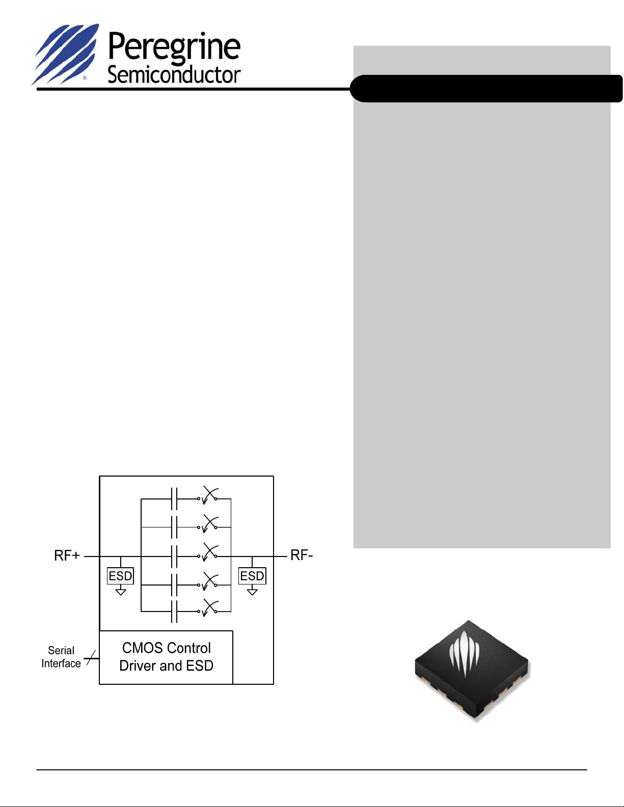
The PE64102 is a DuNE™-enhanced Digitally Tunable
Capacitor (DTC) based on Peregrine’s UltraCMOS
®
technology. DTC products provide a monolithically
integrated impedance tuning solution for demanding
RF applications. They also offer a linear capacitance
change versus tuning state and excellent harmonic
performance compared to varactor-based tunable
solutions.
This highly versatile product can be mounted in series
or shunt configurations and uses a 3-wire (SPI
compatible) serial interface. It has a high ESD rating of
2 kV HBM on all ports making this the ultimate in
integration and ruggedness. The DTC will be offered in
a standard 12-lead 2.0 x 2.0 x 0.55 mm QFN
commercial package.
Peregrine’s DuNE™ technology enhancements deliver
high linearity and exceptional harmonics performance.
It is an innovative feature of the UltraCMOS
®
process,
providing performance superior to GaAs with the
economy and integration of conventional CMOS.
UltraCMOS
®
Digitally Tunable Capacitor
(DTC) 100 - 3000 MHz
Features
3-wire (SPI compatible) 8-bit serial interface
with built-in bias voltage generation and
stand-by mode for reduces power
consumption
DuNE
TM
-enhanced UltraCMOS
®
device
5-bit 32-state Digitally Tunable Capacitor
C = 1.88 - 14.0 pF (7.4:1 tuning ratio) in
discrete 391 fF steps
RF power handing (up to 26 dBm, 6 V
PK
RF)
and high linearity
High quality factor
Wide power supply range (2.3 to 3.6V) and
low current consumption
(typ. I
DD
= 30 µA @ 2.8V)
Optimized for shunt configuration, but can
also be used in series configuration
Excellent 2 kV HBM ESD tolerance on
all pins
Applications include:
Antenna tuning
Tunable filters
Phase shifters
Impedance matching
PE64102
Product Specification
Figure 1. Functional Block Diagram
71-0066-01
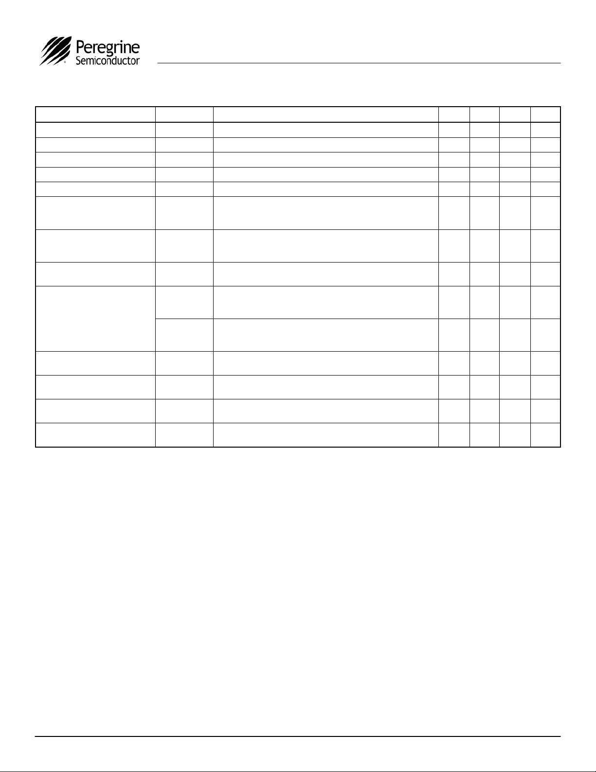
Figure 2. Package Type
12-lead 2 x 2 x 0.55 mm QFN
剩余12页未读,继续阅读
资源评论


