


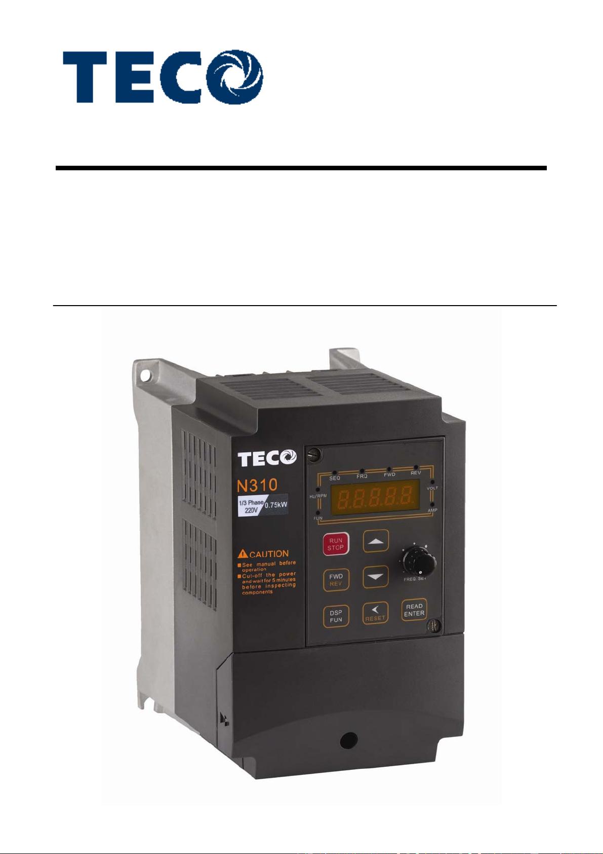
Microprocessor Controlled
I G B T Drive
Inverter Motor Speed Regulator
Operating Manual
N310 Serise
200V class
400V class
0.4~2.2KW
(1.2~4.0KVA)
0.75~55KW
(1.7~110KVA)

iv
Quick Start Guide
This guide is to assist in installing and running the inverter to verify that the drive and
motor are working properly. Starting, stopping and speed control will be from the
keypad. If your application requires external control or special system programming,
consult the N310 Instruction Manual supplied with your inverter.
Step 1 Before Starting the Inverter
Please review Preface and Safety Precautions (page 0-1 through 1-3) of the N310
Instruction Manual. Verify drive was installed in accordance with the procedures as
described in N310 Ambient Environment and Installation on pages 3-1 through 3-8. If
you feel this was abnormal, do not start the drive until qualified personnel have
corrected the situation. (Failure to do so could result in serious injury.)
z Check inverter and motor nameplates to determine that they have the same
HP and voltage ratings. (Ensure that full load motor amps do not exceed
that of the inverter.)
z Remove the terminal cover to expose the motor and power terminals.
a. Verify that AC power is wired to L1, L2, and L3 (pages 3-12).
b. Verify that Motor leads are connected to T1, T2, and T3 (pages 3-12).
(The two leads may need to be reversed if motor rotation is not correct.
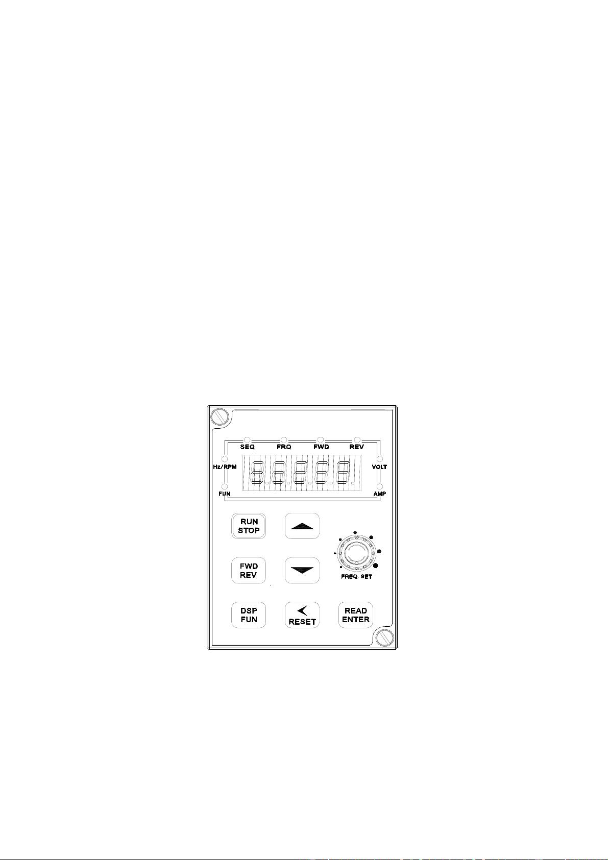
1. Four action of FUN, Hz/RPM, VOLT, AMP LED and display of five 7-segment
displays, refer to operation description of the keypad.
2. SEQ LED: 00-03(or 00-04) =1/2/3, LED Lit.
3. FRQ LED: 00-05(or 00-06) = 1/2/3/4, LED Lit
4. FWD LED: Forward Direction, LED action (Flash in stop, Keep Lit in operation).
5. REV LED: Reverse Direction, LED action (Flash in stop, Keep Lit in operation).

v
Step 2 Apply Power to the Drive
z Apply AC power to the Drive and observe Operator. Five 7-segment Display
should read Power Voltage for 2 seconds and then read Frequency/Speed,
5.00. Five 7-segment Display and FWD LED should be flashed all the time.
Step 3 Check Motor Rotations without Load
z Press RUN key (FWD LED should light); five 7-segment Display should run
from 0.00 to 5.00.
z Check motor rotation.
If it is not correct:
Press STOP key. Remove AC power. Wait for LED “charge” lamp to extinguish.
Reverse motor leads T1 and T2.Restart the drive and check new rotation.
Step 4 Check Full Speeds at 50Hz/60Hz
z Frequency/Speed can be changed by pressing the up or down Arrow keys.
To move right or left for next digit, press “<” key.
Press the READ / ENTER key to set the speed.
z Set frequency up to 50Hz/60Hz in accordance with the last rule.
z Press RUN key. Check drives acceleration to full speed.
z Press STOP key to stop drive and check deceleration.
Step 5 Other Operations
Run command selection: 00-03(or 00-04)
Frequency command selection: 00-05(or 00-06)
For information, see N310 Instruction Manual.
Please refer to the following pages:
Set Control Mode (Vector, V/F) .............................…. p. 4-07
Set Motor Rated Current .......................................…. p. 4-13
Set Accel ......................................................................p. 4-08
Set Decel ..................................................................... p. 4-08
Set Max Speed ............................................................ p. 4-08
Set Min Speed ............................................................. p. 4-08
iv
Quick Start Guide
This guide is to assist in installing and running the inverter to verify that the drive and
motor are working properly. Starting, stopping and speed control will be from the
keypad. If your application requires external control or special system programming,
consult the N310 Instruction Manual supplied with your inverter.
Step 1 Before Starting the Inverter
Please review Preface and Safety Precautions (page 0-1 through 1-3) of the N310
Instruction Manual. Verify drive was installed in accordance with the procedures as
described in N310 Ambient Environment and Installation on pages 3-1 through 3-8. If
you feel this was abnormal, do not start the drive until qualified personnel have
corrected the situation. (Failure to do so could result in serious injury.)
z Check inverter and motor nameplates to determine that they have the same
HP and voltage ratings. (Ensure that full load motor amps do not exceed
that of the inverter.)
z Remove the terminal cover to expose the motor and power terminals.
a. Verify that AC power is wired to L1, L2, and L3 (pages 3-12).
b. Verify that Motor leads are connected to T1, T2, and T3 (pages 3-12).
(The two leads may need to be reversed if motor rotation is not correct.
1. Four action of FUN, Hz/RPM, VOLT, AMP LED and display of five 7-segment
displays, refer to operation description of the keypad.
2. SEQ LED: 00-03(or 00-04) =1/2/3, LED Lit.
3. FRQ LED: 00-05(or 00-06) = 1/2/3/4, LED Lit
4. FWD LED: Forward Direction, LED action (Flash in stop, Keep Lit in operation).
5. REV LED: Reverse Direction, LED action (Flash in stop, Keep Lit in operation).

v
Step 2 Apply Power to the Drive
z Apply AC power to the Drive and observe Operator. Five 7-segment Display
should read Power Voltage for 2 seconds and then read Frequency/Speed,
5.00. Five 7-segment Display and FWD LED should be flashed all the time.
Step 3 Check Motor Rotations without Load
z Press RUN key (FWD LED should light); five 7-segment Display should run
from 0.00 to 5.00.
z Check motor rotation.
If it is not correct:
Press STOP key. Remove AC power. Wait for LED “charge” lamp to extinguish.
Reverse motor leads T1 and T2.Restart the drive and check new rotation.
Step 4 Check Full Speeds at 50Hz/60Hz
z Frequency/Speed can be changed by pressing the up or down Arrow keys.
To move right or left for next digit, press “<” key.
Press the READ / ENTER key to set the speed.
z Set frequency up to 50Hz/60Hz in accordance with the last rule.
z Press RUN key. Check drives acceleration to full speed.
z Press STOP key to stop drive and check deceleration.
Step 5 Other Operations
Run command selection: 00-03(or 00-04)
Frequency command selection: 00-05(or 00-06)
For information, see N310 Instruction Manual.
Please refer to the following pages:
Set Control Mode (Vector, V/F) .............................…. p. 4-07
Set Motor Rated Current .......................................…. p. 4-13
Set Accel ......................................................................p. 4-08
Set Decel ..................................................................... p. 4-08
Set Max Speed ............................................................ p. 4-08
Set Min Speed ............................................................. p. 4-08


