没有合适的资源?快使用搜索试试~ 我知道了~
资源推荐
资源详情
资源评论
Background
The IEEE 802.1D bridge protocol specifies how the packets are switched between LAN
segments. As mentioned in this specification, for the packets addressed with multicast destination,
switch always forward copies of them to each of the non ingress ports in forwarding state, just like
it done for broadcast packets. That means whether the nodes connecting to the switch ports are
interesting in the multicast packets, they always receive all of these packets. As we know, the
original purpose for multicast is send the information to those really interest for it, to broadcast the
multicast frames is against to this purpose. Further more, the multicast currently is used to carry
the videos, voices, etc. These applications will occupy more and more bandwidth, if the multicast
frames are forwarded as broadcast same as before, the network nodes will be drawn in the
multicast waves soon.
To avoid such kind of situation, many mechanisms are introduced into the L2 switch devices,
such as IGMP snooping, IGMP proxy, controllable multicasting, and so on. In our product, some
of them will be implemented to protect the end users from the annoying from the multicast storm.
And one of them will be described in this document, that is IGMP snooping.
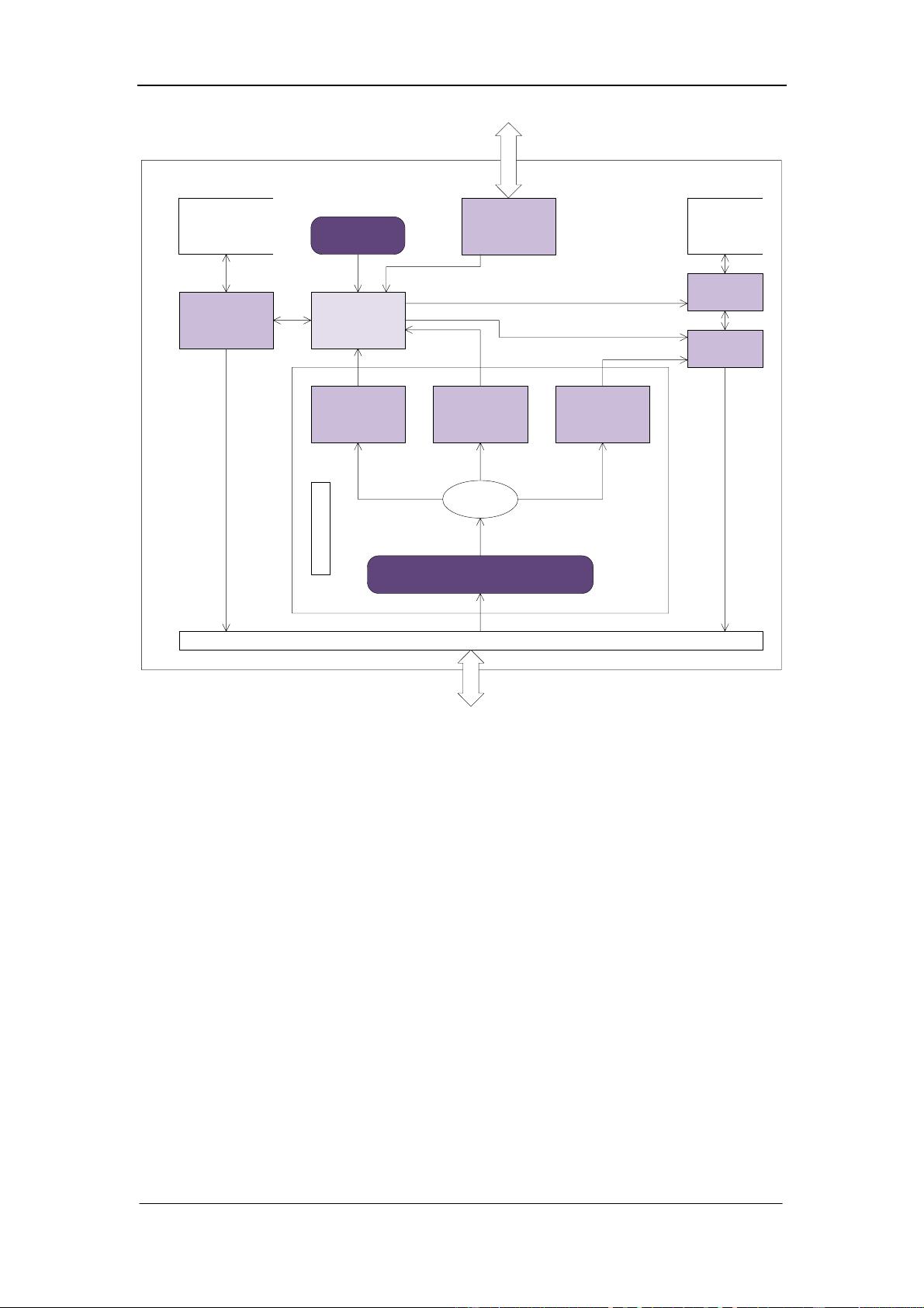
The block surrounded with the dash line shows the position of the IGMP module in the whole
system. The module is divided into two major parts: one is the IGMP core module, the other is
IGMP control logic. The IGMP core module is mainly responding for the IGMP protocol frames
sniffer, switch forward table control and membership management. On the other hand, the IGMP
control logic is in charge of the procession to the customer control request to the IGMP module.
IGMP control logic receives the customer control request, and translates them to the IGMP
core through system call ioctl, and show the result to the customer. For IGMP core module, on one
hand, it will sniffer the IGMP protocol frames passing through the switch, and maintain the state
of the membership, then manage the switch forward table according to the state, on the other hand,
it will accept the control requests from the control logic, and change the current behavior
according to these requests.
Module Design
As mentioned in the previous section, there are six elements need to be implemented for
IGMP module. In all this elements, the IGMP core module is the most important one. It handles
the whole module state transition, controls the switch behavior, and responses to the customer
control requests. We can regard it as the brain of the IGMP module, so that the design of it will
affect and decide the other elements’ design. For the IGMP core is so important that we will
describe the mechanism of it, after then we define the other elements one by one.
IGMP Data Flow Control Mechanism
As shown in the figure, the data flow of the IGMP module is divided into two parts, one is
control flow, the other is multicast data flow. The control flow includes all kinds of the IGMP
protocol messages, such as ‘query’, ‘report’, ‘leave’ and so on. All of the control messages should
be sent to IGMP control block at first, then forwarded to the ports decided by IGMP control block.
IGMP control block is also in charge of the data flow control according to the IGMP control
messages.
When the IGMP snooping function enabled, it will block all of the multicast streams ingress
from the router ports and uplink ports (This is a general sense, but for IGMPv3 compatible, there
may be some special procession, this will be discussed later), while a join report to a group ingress
from a host port is snooped, the corresponding multicast stream will be sent to that port with a
specified time window (so called aging time). If the time window has elapsed and there is no more
report snooped, the stream will be stop to send to the port.
Beside the aging time, a query to a group will start an additional time window according to
the maximum response time embedded in the query. In this time window, if the aging time
window has elapsed, the event will be ignored. If the query time window has elapsed and no more
report is received, the multicast stream will be stopped to send to that port.
IGMP Core Element
This element implements a serious of logic to satisfy the recommends described by the
RFC4541, as listed below:
Type No Rules
1
A snooping switch should forward IGMP Membership Reports only
to those ports where multicast routers are attached
2
IGMP networks may also include devices that implement
"proxy-reporting", in which reports received from downstream hosts
are summarized and used to build internal membership states
3
The switch that supports IGMP snooping must flood all
unrecognized IGMP messages to all other ports and must not
attempt to make use of any information beyond the end of the
network layer header
4
An IGMP snooping switch should be aware of link layer topology
changes caused by Spanning Tree operation
Control
(IGMP forwarding)
5
An IGMP snooping switch must not make use of information in
IGMP packets where the IP or IGMP headers have checksum or
integrity errors
6
The snooping switch must not rely exclusively on the appearance of
IGMP Group Leave announcements to determine when entries
should be removed from the forwarding table
1
Packets with a destination IP address outside 224.0.0.X which are
not IGMP should be forwarded according to group-based port
membership tables and must also be forwarded on router ports
2
Packets with a destination IP (DIP) address in the 224.0.0.X range
which are not IGMP must be forwarded on all ports
3
An unregistered packet is defined as an IPv4 multicast packet with a
destination address which does not match any of the groups
announced in earlier IGMP Membership Reports
4
All non-IPv4 multicast packets should continue to be flooded out to
all remaining ports in the forwarding state as per normal IEEE
bridging operations
5
IGMP snooping switches may maintain forwarding tables based on
either MAC addresses or IP addresses
6
Switches which rely on information in the IP header should verify
that the IP header checksum is correct
Data
7
When IGMPv3 "include source" and "exclude source" membership
reports are received on shared segments, the switch needs to forward
the superset of all received membership reports on to the shared
segment
IGMP Receive thread
IGMP frame
analyzer
IGMP V1/V2
handler
IGMP V3 handler
IGMP Unknown
handler
IGMP packet
transmission
IGMP Abstract Layer Interfaces
IGMP State
machine
IGMP group
membership
management
IGMP Timer
thread
Membership
database
Portmap
database
IGMP control
handler
IGMP Rx Module
IGMP port
map
Management
The above figure describes the working flow of the IGMP core element, as we see, the IGMP
receive thread is polling the IGMP frames through the IGMP abstract layer interface. When a
frame is retrieved, the Rx thread passes it to the IGMP frame analyzer, who will parse the frame,
and decide which handler should be called according to the content in the frame. The whole
module is registered as a Linux character device into the operation system.
Currently we only support IGMP V1/V2 in this module, and IGMP V2 is fully compatible
with the V1, so that we combine them into one handler. But we may support IGMP V3 in the
future, so we add a V3 handler in the core element, it only bypass the IGMP messages currently.
The IGMP unknown handler will pass the received frame to all of the remaining switch ports, just
as mentioned in the RFC4541.
The IGMP state machine is a core in core, it maintains the group state, updates the
membership through the membership management unit, updates the port map database, and
transmits IGMP frames according to the current state. Later we will discuss this state machine in
detail.
The IGMP group membership management unit provides a mechanism to control the
multicast groups. It maintains the membership database and controls the switch hardware through
the IGMP abstract layer.
The IGMP packet transmission unit is used to handle frame transmission request, it will
transmit the IGMP frames to the specified switch ports according to the port map database and the
request type. As shown in the figure, the port map database is managed by the port map
management unit, IGMP control handler and state machine may update it through the management
unit.
The IGMP control handler receives commands from the upper layer application, and updates
the corresponding units according to the commands.
The timer thread is a heart beat generator, it will be wake up at a static interval, at this time
the state machine will be pushed to update the related states.
IGMP State Machine
The IGMP state machine is in charge of the port state maintenance, for every port, there is a
state machine. It will manage the other units through several interfaces according to the port state.
It is somewhat like a processor.
All of the event will be put into the state machine through the state machine selector. It will
choose one or several port state machine to carry out the state transition. As shown in the diagram,
three types of interface are connected to the selector. Obviously, there should be a semaphore to
synchronize the access to state machine in the selector.
The timer thread will send a heart beat to the state machine through the timer interface every
100ms, the state machines then update the timers for every ports, if any timer is up to date, some
operations will be done, such as send a query, delete a membership and so on.
When an IGMP frame comes in, it will be parsed by the IGMP handler, which will abstract
the frame information and pass the information to state machine through the frame process
interface. Then the state machine will update the current state according to the information and
finally to control the membership or transmit some frames.
剩余21页未读,继续阅读
资源评论
- xidianjunnan2012-03-20全是英文 而且有些图片和文字都是乱的(重叠或是显示不全) 不怎么好
- lxahnu2012-02-20里面的图片里面的文字很多都没有了,全部是英语,感觉不是很好
- gzlzxmh2012-10-11英文版本有乱码,不过还是谢谢了,可以参考一下!
dayushu
- 粉丝: 1
- 资源: 24
上传资源 快速赚钱
- 我的内容管理 展开
- 我的资源 快来上传第一个资源
- 我的收益 登录查看自己的收益
- 我的积分 登录查看自己的积分
- 我的C币 登录后查看C币余额
- 我的收藏
- 我的下载
- 下载帮助
最新资源
- 信呼OA系统2.1.7版源码
- 3122080306 邹子轩 实验报告二.docx
- 基于STM32 NUCLEO板设计彩色LED照明灯(纯cubeMX开发)(大赛作品,文档完整,可直接运行)
- 发那科工业机器人保养大全
- Sphere.h
- REMD固有时间尺度分解信号分量可视化(Matlab完整源码和数据)
- 嵌入式系统双单片机STC89C52+STC15W104多功能学习板电路图可扩展 适用于单片机初学者和教学
- 基于STM32蓝牙控制小车系统设计(硬件+源代码+论文)大赛作品
- XILINXFPGA源码基于Spartan3火龙刀系列FPGA开发板VGA测试例程
- Java聊天室的设计与实现【尚学堂·百战程序员】
资源上传下载、课程学习等过程中有任何疑问或建议,欢迎提出宝贵意见哦~我们会及时处理!
点击此处反馈
安全验证
文档复制为VIP权益,开通VIP直接复制
信息提交成功