串口转RJ11接口[定义].pdf
版权申诉
183 浏览量
2021-10-12
02:11:34
上传
评论
收藏 102KB PDF 举报

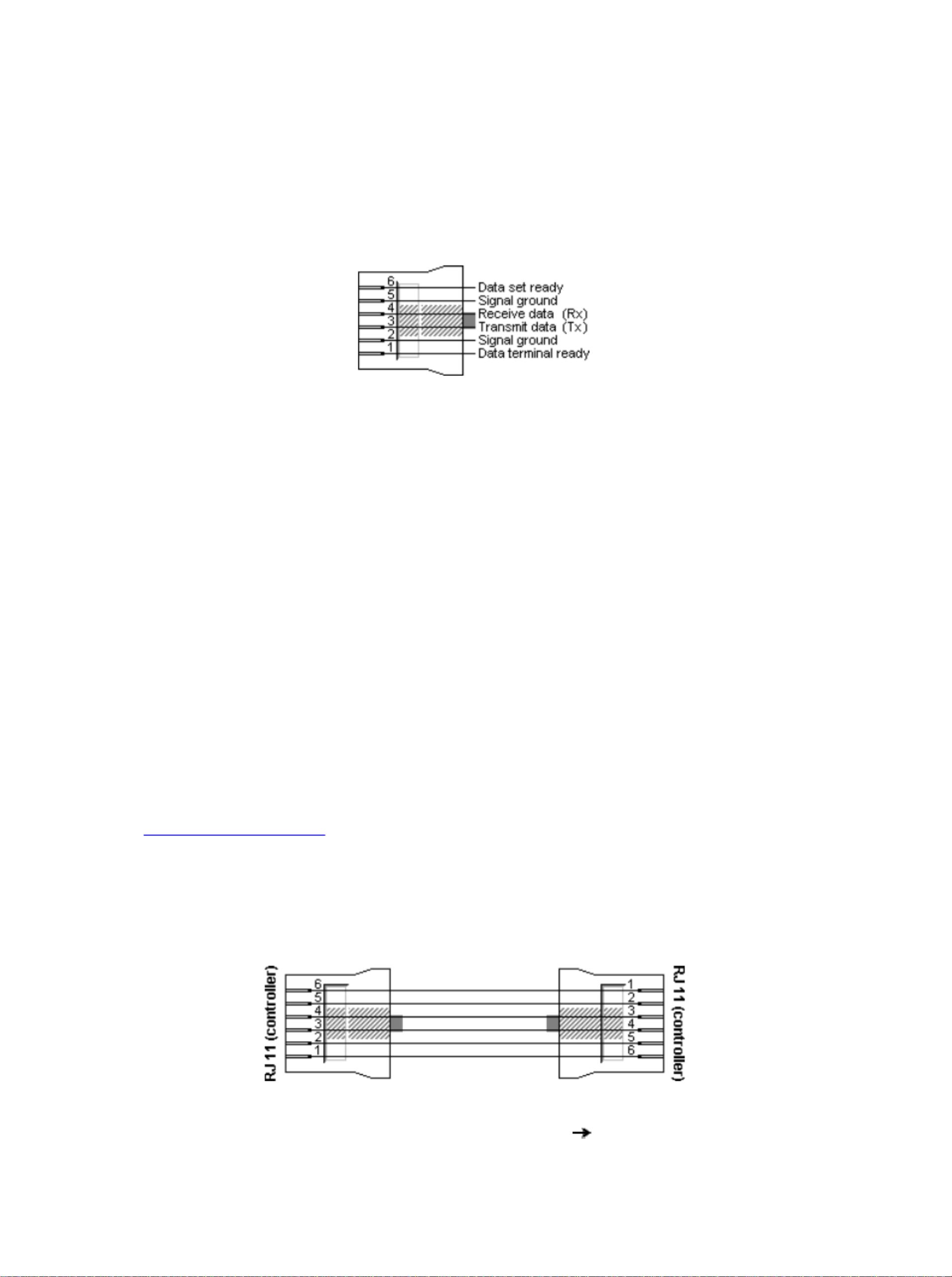
Unitronics PLC pin assignment for the RJ11 socket
The RJ11 socket in the Unitronics PLCs provides six signal pins. In RS232
mode all pins are used for RS232 signals. When in RS485 mode, only pin 1
and 6 are reassigned. The central four pins remain their original RS232
functionality.
Unitronics PLC RJ11 pin assignment
Pin RS232 function RS485 function
1 DTR A (+)
2 Signal ground
RS232 signal
3 TxD
RS232 signal
4 RxD
RS232 signal
5 Signal ground
RS232 signal
6 DSR B ( –)
Basic Unitronics RJ11 connection cables
The symmetrical pin layout of the RJ11 sockets on the Unitronics PLCs
allows an easy way of interconnecting the PLCs with both RS232and RS485
communications. For RS232 a crossover cable is used where pin 1 is
connected with pin 6 at the other connector, pin 2 with pin 5, etc. This
interconnects the transmit and receive signals of both PLCs, and also the
handshaking signals DTR and DSR. If handshaking is not necessary, an
ordinary 4 wire telephone cable could be used, provided that the pins are
cross-connected as shown in the picture below. Otherwise a full 6 wire
cable must be used. Two wire telephone cables will not function because
in that case the ground signal levels on both sides will be floating.
Unitronics RJ11 RS232 crossover cable
RJ11 plug 1 RJ11 plug 2 Function
1 6 DTR DSR
资源评论


czq131452007
- 粉丝: 2
- 资源: 12万+

下载权益

C知道特权

VIP文章

课程特权
开通VIP


最新资源
- VIVADO中UART IP核使用
- 【深度学习实际案例解析】深度学习实际案例解析
- 封装swagger组件,提供全新UI以及无状态登录接口调用解决方案
- 小龙坎支局2024年4月渠道积分核对数据.xlam
- onlyoffice搭建及与alist使用的view.html
- Quadcopter-UAV-attitude-estimation-linux常用命令大全demo
- Quadcopter-UAV-attitude-estimation-based-on-数据库课程设计
- pbdlib-python-master.zip
- 43904245495352013_base.apk
- 基于springboot+vue + redis的工作流审批系统
资源上传下载、课程学习等过程中有任何疑问或建议,欢迎提出宝贵意见哦~我们会及时处理!
点击此处反馈


