没有合适的资源?快使用搜索试试~ 我知道了~
Ipsaki D,Voutetakis S,Seferlis P,et al. Power management strateg
0 下载量 153 浏览量
2023-06-21
20:39:18
上传
评论
收藏 574KB PDF 举报
温馨提示
试读
15页
Ipsaki D,Voutetakis S,Seferlis P,et al. Power management strategies for a stand-alone power system using renewable sources and hydrogen storage. International Journal of Hydrogen Ipsaki D,Voutetakis,Seferlis P,等,《使用可再生能源和储氢的独立电力系统的电力管理策略》。国际氢杂志
资源推荐
资源详情
资源评论
Power management strategies for a stand-alone
power system using renewable energy sources and
hydrogen storage
Dimitris Ipsakis
a,1
, Spyros Voutetakis
a,
*, Panos Seferlis
a,2
,
Fotis Stergiopoulos
a
, Costas Elmasides
b
a
Chemical Process Engineering Research Institute (C.P.E.R.I.), CEntre for Research and Technology Hellas (CE.R.T.H.),
P.O. Box 60361, 57001 Thermi-Thessaloniki, Greece
b
Systems Sunlight SA, 67200, Neo Olvio, Xanthi, Greece
article info
Article history:
Received 22 November 2007
Received in revised form
28 May 2008
Accepted 4 June 2008
Available online 4 September 2008
Keywords:
Renewable energy sources
Stand-alone power system
PEM Electrolyzer
PEM fuel cell
Lead-acid accumulator
Hydrogen production
Power management strategy
abstract
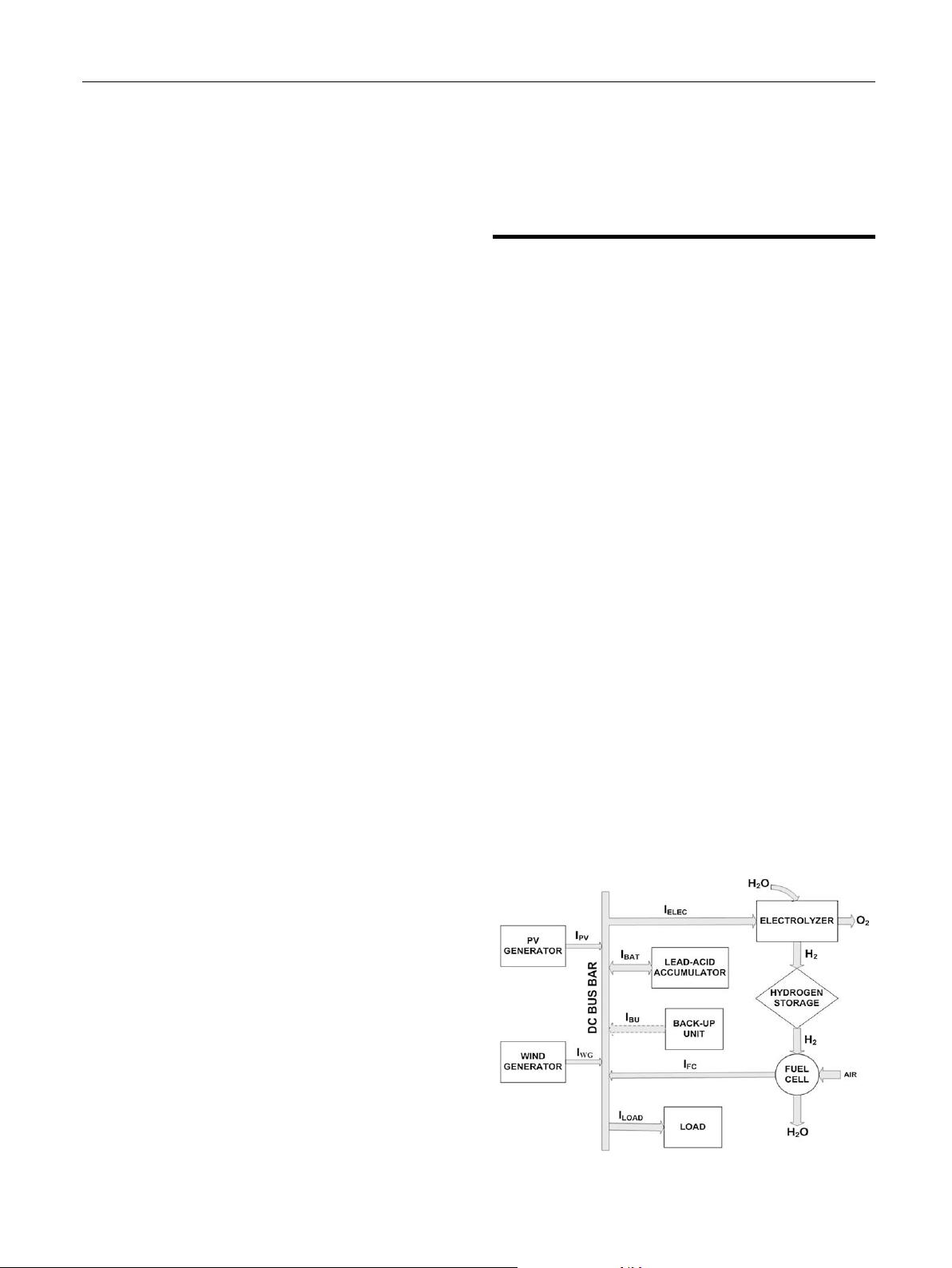
A stand-alone power system based on a photovoltaic array and wind generators that stores
the excessive energy from renewable energy sources (RES) in the form of hydrogen via
water electrolysis for future use in a polymer electrolyte membrane (PEM) fuel cell is
currently in operation at Neo Olvio of Xanthi, Greece. Efficient power management strate-
gies (PMSs) for the system have been developed. The PMSs have been assessed on their
capacity to meet the power load requirements through effective utilization of the electro-
lyzer and fuel cell under variable energy generation from RES (solar and wind). The evalu-
ation of the PMS has been performed through simulated experiments with anticipated
conditions over a typical four-month time period for the region of installation. The key
decision factors for the PMSs are the level of the power provided by the RES and the state
of charge (SOC) of the accumulator. Therefore, the operating policies for the hydrogen
production via water electrolysis and the hydrogen consumption at the fuel cell depend
on the excess or shortage of power from the RES and the level of SOC. A parametric sensi-
tivity analysis investigates the influence of major operating variables for the PMSs such as
the minimum SOC level and the operating characteristics of the electrolyzer and the fuel
cell in the performance of the integrated system.
ª 2008 International Association for Hydrogen Energy. Published by Elsevier Ltd. All rights
reserved.
1. Introduction
Power systems based on RES offer off-grid energy supply for
various applications, such us electrification of rural and
remote areas with problematic grid connection, powering of
telecommunication stations, energy intensive desalination
of water and water pumping for irrigation or drinking
purposes. These systems are usually a combination of photo-
voltaic systems (PV-systems), wind generators and diesel
generators [1–4]. Sometimes they are accompanied by micro-
hydro generators that utilize water potential energy to
produce electricity [5–7].
* Corresponding author. Tel.: þ30 2310 498 317; fax: þ30 2310 498 380.
E-mail address: paris@cperi.certh.gr (S. Voutetakis).
1
Department of Chemical Engineering, Aristotle University of Thessaloniki, P.O. Box 1517, 54124 Thessaloniki, Greece.
2
Department of Mechanical Engineering, Aristotle University of Thessaloniki, P.O. Box 484, 54124 Thessaloniki, Greece.
Available at www.sciencedirect.com
journal homepage: www.elsevier.com/locate/he
0360-3199/$ – see front matter ª 2008 International Association for Hydrogen Energy. Published by Elsevier Ltd. All rights reserved.
doi:10.1016/j.ijhydene.2008.06.051
international journal of hydrogen energy 34 (2009) 7081–7095
Global warming is considered as one of the most critical
environmental problems that people will face in the next
50 years [8]. The use of RES for the production of electrical
energy can contribute significantly to the reduction of green-
house emissions such as carbon dioxide and nitrogen oxides
and protect the environment from further degradation. More-
over, solar and wind energy is abundant, free, clean and inex-
haustible. Other advantages of PV-systems and wind
generators include the long lifetime and low maintenance
requirements for both systems [9]. The time variations of the
weather conditions, however, require the design of a robust
system in order to compensate for the fluctuations of the
available energy from RES. Traditionally, deep-cycle lead-
acid accumulators have been used as the means of short-
term energy storage. Accumulators though, have a relatively
small lifespan (around 3–6 years) and due to their heavy utili-
zation affect the operation and maintenance costs of the
system. Therefore, utilization of surplus energy from RES in
a water electrolyzer for hydrogen production and subsequent
use in a fuel cell in cases of shortage of energy provides
a viable, efficient and promising alternative storage of energy
[9–16]. Such integrated stand-alone systems have been
recently developed and implemented in various locations
around the world [15,17,18].
The design, analysis and optimization of such systems
require the development of mathematical models for all indi-
vidual components [19–21]. Accurate models predict the daily
profiles of produced energy from PV-systems and wind gener-
ators based on meteorological data [22,23]. Dynamic PEM
electrolyzer and hydrogen storage analysis calculate the
necessary power for hydrogen production and storage pres-
sure in pressurized tanks [24]. Several models predict fuel
cell characteristics with empirical equations [22,25–27] and
rigorous mathematical dynamic models [28]. The proper
sizing of the various subsystems is a major challenge that
depends on weather conditions at the place of installation,
the selected operating policy and of course economic data
(e.g., cost of purchase, maintenance, operation and so forth).
Numerous studies have been published on this subject that
deal with different configurations of stand-alone power
systems [9,16,29–32]. Optimization strategies based on cost
minimization of the integrated system utilizing a short-term
Nomenclature
A
elec
electrode area, m
2
A
w
wind generator swept area, m
2
c
p
performance coefficient of the wind generator
F Faraday’s constant, Cb/mol
I
bat
charging/discharging current, A
I
D
diode current for the PV-system, A
I
elec
operation current for the PEM electrolyzer, A
I
L
light current for the PV-system, A
I
o
diode reverse saturation current for the
PV-system, A
I
pv
operation current for the PV-system, A
I
sh
shunt current for the PV-system, A
i current density for the PEM fuel cell, A/m
2
i
o
Tafel parameter for the PEM fuel cell, A/m
2
l parameter for the overvoltage due to mass
transportation limitations for the PEM fuel cell,
m
2
/A
m parameter for the overvoltage due to mass
transportation limitations for the PEM fuel cell, V
n number of mol of hydrogen, mol
n
c
number of cells for the PEM electrolyzer or the PEM
fuel cell
n
e
number of electrons
n
F
Faraday’s efficiency
n
H
2
hydrogen flow rate, mol/s
P shortage or surplus power, J/s
P
Acc
power from/to the accumulator, J/s
P
c1
hydrogen pressure before the compression, bar
P
c2
hydrogen pressure after the compression, bar
P
cr
critical pressure of hydrogen, bar
P
load
power demand of the load, J/s
P
w
output power from the wind generator, J/s
P
pv
output power from the PV-system, J/s
P
RES
produced power from the RES, J/s
P
T
pressure in the storage tanks, bar
PMSs/PMS power management strategies/strategy
R universal gas constant, bar m
3
/mol K
R
s
series resistance for the PV-system, U
R
sh
shunt resistance for the PV-system, U
SOC State of Charge of the accumulator
r resistance for the PEM fuel cell, U m
2
r
i
parameters for the ohmic resistance of the
electrolyte of the PEM electrolyzer, i ¼ 1,2
s
i
parameters for the overvoltage at the electrodes of
the PEM electrolyzer, i ¼ 1,.3
T temperature,
C
T
c1
temperature of the hydrogen before the
compression, K
T
c2
temperature of the hydrogen after the
compression, K
T
cr
critical temperature of hydrogen, K
t
i
parameters for the overvoltage at the electrodes of
the PEM electrolyzer, i ¼ 1,.3
V
c1
volume of the hydrogen before the
compression, m
3
V
c2
volume of the hydrogen after the compression, m
3
V
elec
operation cell voltage for the PEM electrolyzer, V
V
fc
operation cell voltage for the PEM fuel cell, V
V
o
open circuit voltage for the PEM fuel cell, V
V
pv
operation voltage for the PV-system, V
V
rev,elec
reversible voltage for the PEM electrolyzer, V
V
rev,fc
theoretical reversible voltage for the PEM fuel
cell, V
V
T
tank volume, m
3
Greek symbols
a curve fitting parameter for the PV-system, V
a
T
Tafel slope for the PEM fuel cell, V
b blade pitch angle for the wind generator, degree
l tip speed ratio
v
wind
wind speed, m/s
r air density, kg/m
3
international journal of hydrogen energy 34 (2009) 7081–70957082
and a long-term storage system can be proved quite efficient
[29,33–35]. Several power management algorithms that use
models to predict the behavior of stand-alone power systems
have been developed and evaluated based on the achieved
performance [32,36,37]. The experience gained from the oper-
ation of different stand-alone power systems across the world
is a valuable resource for the selection of a proper operating
policy in a similar system [38–45]. The main conclusion is
that PMSs strongly affect the lifetime of the various subsys-
tems and in particular the lifetime of the accumulator, the
electrolyzer and the fuel cell. The key decisions in a PMS are
based on the SOC levels of the accumulator [22,35,37,46]. The
minimum SOC limit, SOC
min
, designates the operation of the
fuel cell and the maximum limit, SOC
max
, regulates the oper-
ation of the electrolyzer. The operation of the electrolyzer can
be supported either solely by the RES or by the RES and the
accumulator. In some cases, as described in Refs. [22,35,37],
a hysteresis band was used around those limits that would
ensure a smoother operation for the units.
Nevertheless, little is reported about the influence that key
variables like the operation limits of SOC of the accumulator
and the output power of the fuel cell have on the operation
time and operation variables (e.g. hydrogen inventory) of the
stand-alone power system, but caution was mainly given to
the operation of the accumulator as a sensitive subsystem.
For example, low SOC
min
limits (increased depth of discharge,
DOD) might lead to increased hydrogen inventory, but at the
expense of more intense usage of the accumulator [46]. The
identification of such key variables could be used in optimiza-
tion studies that would take into account the operation costs
along with the key variables and guide the designer to suitable
decisions on enhancing the performance of the system for an
economical and reliable operation. In the present work, three
PMSs are proposed that ultimately aim to ensure the reliable
satisfaction of the system load requirement and safeguard
the units from undesirable operating conditions. The perfor-
mance of the entire power system under each PMS is then
estimated and assessed under variable conditions. Hence,
the interactions among the various components of the power
system are being fully explored and analyzed. The assessment
criteria include the satisfaction of the specifications of the
subsystems (electrolyzer, fuel cell, and accumulator) and the
maximization of the efficient power utilization. The key deci-
sion parameters in the PMS are the level of the power provided
by the RES and the SOC levels of the accumulator. Therefore,
the operating policies of the hydrogen production via water
electrolysis and the hydrogen consumption in the fuel cell
mainly depend on the excess or shortage of energy from the
RES and the level of SOC for the accumulator. Constraints
associated with the operation of the electrolyzer and the
fuel cell are also taken into consideration. The proposed
logical block diagrams are given in such a way that the imple-
mentation in various simulation programs is quite easy to
handle.
The structure of the paper is as follows: in Section 2 the
mathematical models employed for each subsystem are
briefly described. The major equations are provided and the
key model parameters are defined. Section 3 presents the
proposed PMSs for the integrated system through logical block
diagrams and provides the implementation details. Section
4 reports the simulated results and evaluates the performance
of each PMSs towards certain criteria. A sensitivity analysis of
the system performance with respect to key decision parame-
ters attempts to identify the optimal operating factors for the
PMSs in Section 5.
2. Stand-alone power system: system
description and unit modeling
An application utilizing solar and wind energy with hydrogen
production through water electrolysis, storage and utilization
in fuel cell is currently in operation installed at Neo Olvio of
Xanthi, Greece. Fig. 1 shows a layout of the stand-alone power
system. The RES production subsystem comprises a PV-array
with a nominal capacity of 5 kW
p
and three wind generators
rated at 3 kW
p
in total. The system is attached to a 1 kW
load. Surplus energy from RES can potentially be used to oper-
ate a PEM electrolyzer, rated at 4.2 kW
p
. The produced
hydrogen is stored in cylinders under medium pressure with
total volume 6 m
3
(equivalent energy is around 190 kW h,
giving about 8 days of autonomy). In case that RES fail to
meet the load specification, a PEM fuel cell rated at 4 kW
p
that utilizes the stored hydrogen can be used as an alternative
energy source. The produced water from the fuel cell is
recycled in a closed loop back to the water storage tank for
use in the electrolyzer. Furthermore, in order to account for
short-term produced energy fluctuations and ensure
smoother operation of the system, a lead-acid accumulator
with a total capacity of 3000 A h at 48 V has been installed.
Optionally, a back up unit (diesel generator or grid) can be
used in order to cover the electrical needs during periods of
low RES energy and hydrogen inventory. Furthermore, power
electronic converters are employed for power conditioning
and integration of the various subsystems through a 48 V DC
bus. Thus, in order to assess the performance of the integrated
system, detailed and accurate mathematical models are
employed for the simulation of each subsystem in the inte-
grated system.
Fig. 1 – Block diagram of the proposed stand-alone power
system.
international journal of hydrogen energy 34 (2009) 7081–7095 7083
剩余14页未读,继续阅读
资源评论
上山砍菜
- 粉丝: 0
- 资源: 225
上传资源 快速赚钱
- 我的内容管理 展开
- 我的资源 快来上传第一个资源
- 我的收益 登录查看自己的收益
- 我的积分 登录查看自己的积分
- 我的C币 登录后查看C币余额
- 我的收藏
- 我的下载
- 下载帮助
安全验证
文档复制为VIP权益,开通VIP直接复制
信息提交成功