没有合适的资源?快使用搜索试试~ 我知道了~
LTC4054的典型应用手册(电源管理芯片)
5星 · 超过95%的资源 需积分: 50 60 下载量 39 浏览量
2009-06-06
10:27:17
上传
评论 1
收藏 199KB PDF 举报
温馨提示
试读
16页
特点 高达 800mA 的可编程充电电流 无需 MOSFET、检测电阻器或隔离二极管 用于单节锂离子电池、采用 ThinSOTTM 封装的完整线性充电器 恒定电流/恒定电压操作,并具有可在无过热危险的情况下实现充电速率最大化的热调 节功能* 直接从 USB 端口给单节锂离子电池充电 精度达 ± 1% 的 4.2V 预设充电电压 用于电池电量检测的充电电流监控器输出* 自动再充电 充电状态输出引脚 C/10 充电终止 停机模式下的供电电流为 25µA 2.9V 涓流充电门限 (LTC4054) 可提供无涓流充电器件版本 (LTC4054X) 软起动限制了浪涌电流 采用 5 引脚 SOT-23 封装
资源推荐
资源详情
资源评论
1
LTC4054L-4.2
4054l42f
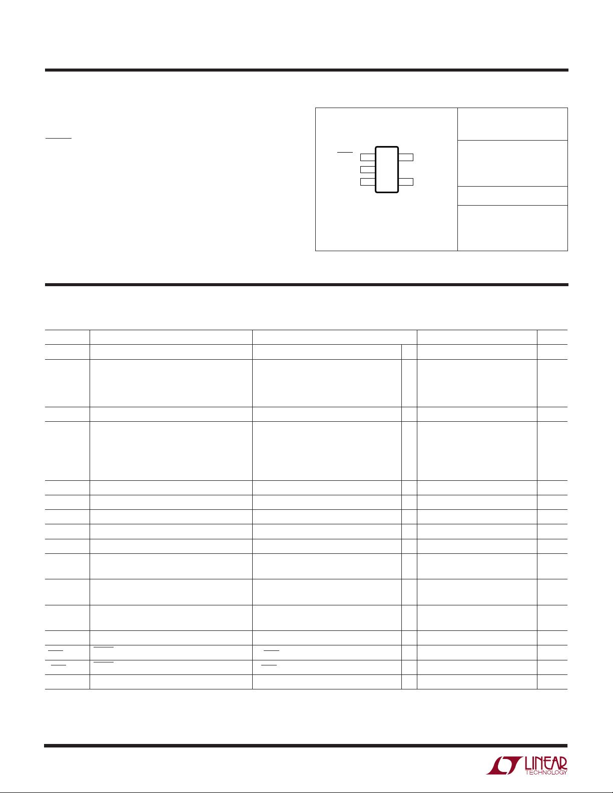
150mA Standalone Linear
Li-Ion Battery Charger in ThinSOT
, LTC and LT are registered trademarks of Linear Technology Corporation.
■
Programmable Charge Current Range:
10mA to 150mA
■
No External MOSFET, Sense Resistor or Blocking
Diode Required
■
Complete Linear Charger in ThinSOT
TM
Package for
Single Cell/Coin Cell Lithium-Ion Batteries
■
Constant-Current/Constant-Voltage Operation with
Thermal Regulation* to Maximize Charge Rate
Without Risk of Overheating
■
Charges Single Cell Li-Ion Batteries Directly
from USB Port
■
Preset 4.2V Charge Voltage with ±1% Accuracy
■
Charge Current Monitor Output for Gas Gauging*
■
Automatic Recharge
■
Charge Status Output Pin
■
C/10 Charge Termination
■
25µA Max Supply Current in Shutdown Mode
■
2.9V Trickle Charge Threshold
■
Soft-Start Limits Inrush Current
■
Available in a 6-Lead Low Profile (1mm)
SOT-23 Package
■
Charger for Li-Ion Coin Cell Batteries
■
Portable MP3 Players, Wireless Headsets
■
Bluetooth Applications
■
Multifunction Wristwatches
ThinSOT is a trademark of Linear Technology Corporation.
*U.S. Patent No. 6,522,118
The LTC
®
4054L is a complete, constant-current/constant-
voltage linear charger for single cell lithium-ion batteries.
Its small size and ability to regulate low charge currents
make the LTC4054L especially well-suited for portable
applications using low capacity rechargeable lithium-ion
coin cells. Furthermore, the LTC4054L is specifically de-
signed to work within USB power specifications.
No external sense resistor is needed, and no blocking di-
ode is required due to the internal MOSFET architecture.
Thermal feedback regulates the charge current to eliminate
thermal overdesign. The charge voltage is fixed at 4.2V, and
the charge current can be programmed externally with a
single resistor. The LTC4054L automatically terminates a
charge cycle when the charge current drops to 1/10th the
programmed value after the final float voltage is reached.
When the input supply (wall adapter or USB supply) is
removed, the LTC4054L automatically enters a low cur-
rent state, dropping the battery drain current to less than
2µA. The LTC4054L can be put into shutdown mode, re-
ducing the supply current to 25µA.
Other features include charge current monitor, undervoltage
lockout, automatic recharge and a status pin to indicate
charge termination and the presence of an input voltage.
V
CC
1.69k
4.2V
COIN CELL
Li-Ion
BATTERY
4054l42 TA01
LTC4054L-4.2
1µF
V
IN
4.5V TO 6.5V
BAT
4
3
90mA
5
2
PROG
GND
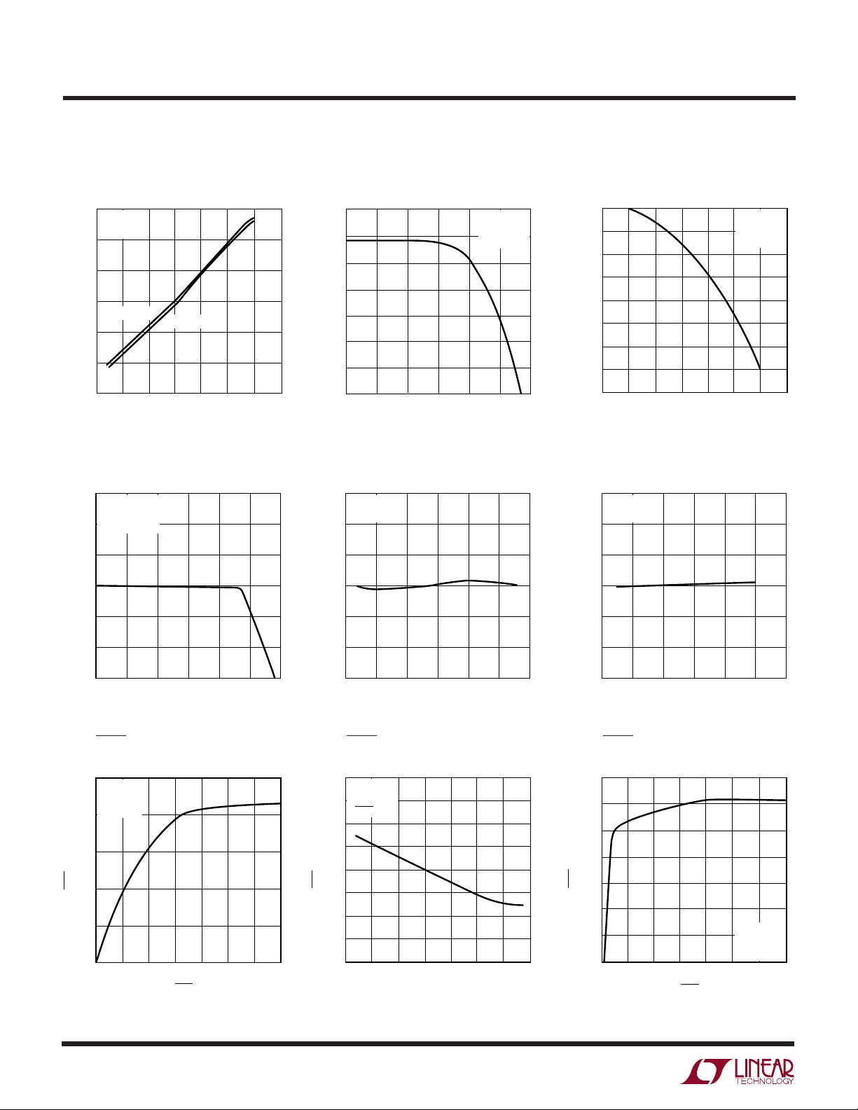
90mA Li-Ion Single Coin Cell Charger
TIME (HOURS)
0
CHARGE CURRENT (mA)
100
90
80
70
60
50
40
30
20
10
0
BATTERY VOLTAGE (V)
4.4
4.3
4.2
4.1
4.0
3.9
3.8
3.7
3.6
3.5
3.4
0.5
1.0
1.25 2.25
4054l42 TA01b
0.25 0.75
1.5
1.75
2.0
CONSTANT
CURRENT
CONSTANT
VOLTAGE
V
CC
= 5V
θ
JA
= 130°C/W
R
PROG
= 1.69k
T
A
= 25°C
Complete Charge Cycle (130mAh Battery)
FEATURES
DESCRIPTIO
U
APPLICATIO S
U
TYPICAL APPLICATIO
U
2
LTC4054L-4.2
4054l42f
(Note 1)
Input Supply Voltage (V
CC
) ....................... –0.3V to 10V
PROG............................................. –0.3V to V
CC
+ 0.3V
CHRG........................................................ –0.3V to 10V
BAT............................................................. –0.3V to 7V
BAT Short-Circuit Duration .......................... Continuous
BAT Pin Current ................................................. 200mA
PROG Pin Current................................................ 1.5mA
Maximum Junction Temperature .......................... 125°C
Operating Temperature Range (Note 2) .. –40°C to 85°C
Storage Temperature Range ................. –65°C to 125°C
Lead Temperature (Soldering, 10 sec).................. 300°C
T
JMAX
= 125°C, θ
JA
= 80°C/W TO 150°C/W
DEPENDING ON PC BOARD LAYOUT (NOTE 3)
ORDER PART
NUMBER
S5 PART MARKING
LTC4054LES5-4.2
LTAFA
SYMBOL PARAMETER CONDITIONS MIN TYP MAX UNITS
V
CC
Supply Voltage ● 4.25 6.5 V
I
CC
Supply Current Charge Mode (Note 4), R
PROG
= 1k ● 1200 2000 µA
Standby Mode (Charge Terminated)
● 200 500 µA
Shutdown Mode (R
PROG
Not Connected, ● 25 50 µA
V
CC
< V
BAT
, or V
CC
< V
UV
)
V
FLOAT
Regulated Output (Float) Voltage 0°C ≤ T
A
≤ 85°C, I
BAT
= 40mA 4.158 4.2 4.242 V
I
BAT
BAT Pin Current R
PROG
= 15k, Current Mode ● 9.3 10 10.7 mA
R
PROG
= 1k, Current Mode ● 142.5 150 157.5 mA
Standby Mode, V
BAT
= 4.2V ● 0 –2.5 –6 µA
Shutdown Mode (R
PROG
Not Connected) ±1 ±2 µA
Sleep Mode, V
CC
= 0V ±1 ±2 µA
I
TRIKL
Trickle Charge Current V
BAT
< V
TRIKL
, R
PROG
= 1k (I
BAT
= 150mA) ● 51525 mA
V
TRIKL
Trickle Charge Threshold Voltage R
PROG
= 15k, V
BAT
Rising 2.8 2.9 3 V
V
TRHYS
Trickle Charge Hysteresis Voltage R
PROG
= 15k 60 80 110 mV
V
UV
V
CC
Undervoltage Lockout Threshold Voltage From V
CC
Low to High ● 3.7 3.8 3.92 V
V
UVHYS
V
CC
Undervoltage Lockout Hysteresis Voltage ● 150 200 300 mV
V
MSD
Manual Shutdown Threshold Voltage PROG Pin Rising ● 1.15 1.21 1.30 V
PROG Pin Falling
● 0.9 1.0 1.1 V
V
ASD
V
CC
– V
BAT
Lockout Threshold Voltage V
CC
from Low to High 70 100 140 mV
V
CC
from High to Low 5 30 50 mV
I
TERM
C/10 Termination Current Threshold R
PROG
= 15k (I
BAT
= 10mA) (Note 5) ● 0.085 0.10 0.115 mA/mA
R
PROG
= 1k (I
BAT
= 150mA) (Note 5) ● 0.088 0.10 0.112 mA/mA
V
PROG
PROG Pin Voltage R
PROG
= 1k, Current Mode ● 0.93 1 1.07 V
I
CHRG
CHRG Pin Weak Pull-Down Current V
CHRG
= 5V 8 20 35 µA
V
CHRG
CHRG Pin Output Low Voltage I
CHRG
= 5mA 0.35 0.6 V
∆V
RECHRG
Recharge Battery Hysteresis Voltage V
FLOAT
– V
RECHRG
100 150 200 mV
The ● denotes specifications which apply over the full operating
temperature range, otherwise specifications are at T
A
= 25°C. V
CC
= 5V, unless otherwise noted.
ABSOLUTE AXI U RATI GS
WWWU
PACKAGE/ORDER I FOR ATIO
UU
W
ELECTRICAL CHARACTERISTICS
Consult LTC Marketing for parts specified with wider operating temperature ranges.
CHRG 1
GND 2
TOP VIEW
S5 PACKAGE
5-LEAD PLASTIC TSOT-23
BAT 3
5 PROG
4 V
CC
3
LTC4054L-4.2
4054l42f
The ● denotes specifications which apply over the full operating
temperature range, otherwise specifications are at T
A
= 25°C. V
CC
= 5V, unless otherwise noted.
ELECTRICAL CHARACTERISTICS
SYMBOL PARAMETER CONDITIONS MIN TYP MAX UNITS
T
LIM
Junction Temperature in Constant 120 °C
Temperature Mode
R
ON
Power FET “ON” Resistance 1.5 Ω
(Between V
CC
and BAT)
t
SS
Soft-Start Time I
BAT
= 0 to I
BAT
=150V/R
PROG
100 µs
t
RECHARGE
Recharge Comparator Filter Time V
BAT
High to Low 0.75 2 4.5 ms
t
TERM
Termination Comparator Filter Time I
BAT
Drops Below I
CHG
/10 400 1000 2500 µs
I
PROG
PROG Pin Pull-Up Current 1.5 3 5 µA
Note 1: Absolute Maximum Ratings are those values beyond which the life
of the device may be impaired.
Note 2: The LTC4054LE-4.2 is guaranteed to meet performance specifica-
tions from 0°C to 70°C. Specifications over the –40°C to 85°C operating
temperature range are assured by design, characterization and correlation
with statistical process controls.
Note 3: See Thermal Considerations.
Note 4: Supply current includes PROG pin current (≈1mA) but does not
include any current delivered to the battery through the BAT pin.
Note 5: I
TERM
is expressed as a fraction of measured full charge current
with indicated PROG resistor.
TYPICAL PERFOR A CE CHARACTERISTICS
UW
PROG Pin Voltage vs Supply
Voltage (Constant Current Mode)
V
CC
(V)
4
V
PROG
(V)
0.9975
1.0000
1.0025
5.5
6.5
4054L G01
0.9950
0.9925
0.9900
4.5 5 6
1.0050
1.0075
1.0100
7
V
CC
= 5V
V
BAT
= 4V
T
A
= 25°C
R
PROG
= 1k
R
PROG
= 15k
TEMPERATURE (°C)
–50
V
PROG
(V)
0.9975
1.0000
1.0025
25
75
4054L G02
0.9950
0.9925
0.9900
–25 0 50
1.0050
1.0075
1.0100
100
V
CC
= 5V
V
BAT
= 4V
R
PROG
= 1k
V
PROG
(V)
0
0
I
BAT
(mA)
30
60
90
120
150
180
0.25 0.5 0.75 1
4054L G03
1.25
V
CC
= 5V
R
PROG
= 1k
T
A
= 25°C
PROG Pin Voltage vs Temperature
(Constant Current Mode)
Charge Current
vs PROG Pin Voltage
4
LTC4054L-4.2
4054l42f
TYPICAL PERFOR A CE CHARACTERISTICS
UW
PROG Pin Pull-Up Current vs
Temperature and Supply Voltage
PROG Pin Current vs PROG Pin
Voltage (Pull-Up Current)
TEMPERATURE (°C)
–50
I
PROG
(µA)
3.3
3.5
3.7
25 75
4054L G04
3.1
2.9
–25 0
50 100 125
2.7
2.5
V
BAT
= 4.3V
V
PROG
= 0V
V
CC
= 6.5V
V
CC
= 4.2V
V
PROG
(V)
2.0
3.5
3.0
2.5
2.0
1.5
1.0
0.5
0
2.3 2.5
4054L G05
2.1 2.2
2.4 2.6
I
PROG
(µA)
V
CC
= 5V
V
BAT
= 4.3V
T
A
= 25°C
V
PROG
(V)
2
I
PROG
(µA)
–50
3.5
4054L G06
–200
–300
2.5 3 4
–350
–400
0
–100
–150
–250
4.5 5 5.5
V
CC
= 5V
V
BAT
= 4.3V
T
A
= 25°C
PROG Pin Current vs PROG Pin
Voltage (Clamp Current)
Regulated Output (Float) Voltage
vs Charge Current
I
BAT
(mA)
0
4.14
V
FLOAT
(V)
4.16
4.18
4.20
4.22
4.26
30
60 90 120
4054L G07
150 180
4.24
V
CC
= 5V
R
PROG
= 600Ω
T
A
= 25°C
Regulated Output (Float) Voltage
vs Temperature
TEMPERATURE (°C)
–50
4.185
V
FLOAT
(V)
4.190
4.195
4.200
4.205
4.215
–25
02550
4054L G08
75 100
4.210
V
CC
= 5V
R
PROG
= 1k
Regulated Output (Float) Voltage
vs Supply Voltage
V
CC
(V)
4
4.185
V
FLOAT
(V)
4.190
4.195
4.200
4.205
4.215
4.5
5 5.5 6
4054L G09
6.5 7
4.210
R
PROG
= 1k
T
A
= 25°C
CHRG Pin I-V Curve
(Strong Pull-Down State)
V
CHRG
(V)
01
0
I
CHRG
(mA)
10
25
2
4
5
4054L G10
5
20
15
3
6
7
V
CC
= 5V
V
BAT
= 4V
T
A
= 25°C
CHRG Pin Current vs Temperature
(Strong Pull-Down State)
TEMPERATURE (°C)
–50
I
CHRG
(mA)
18
25
4054L G11
12
8
–25 0 50
6
4
20
16
14
10
75 100 125
V
CC
= 5V
V
BAT
= 4V
V
CHRG
= 1V
CHRG Pin I-V Curve
(Weak Pull-Down State)
V
CHRG
(V)
0
16
18
22
35
4054L G12
14
12
12
467
10
8
20
I
CHRG
(µA)
V
CC
= 5V
V
BAT
= 4.3V
T
A
= 25°C
剩余15页未读,继续阅读
资源评论
- 梦溪求索2020-06-18很好的资料,谢谢!
- 单纯而勇敢2014-07-11简直好到不能再赞!!!
cg865
- 粉丝: 1
- 资源: 2
上传资源 快速赚钱
- 我的内容管理 展开
- 我的资源 快来上传第一个资源
- 我的收益 登录查看自己的收益
- 我的积分 登录查看自己的积分
- 我的C币 登录后查看C币余额
- 我的收藏
- 我的下载
- 下载帮助
安全验证
文档复制为VIP权益,开通VIP直接复制
信息提交成功