


GND
MCU
I
2
C
Peripheral
3.3 V
ADC
TEMPERATURE
RH
I
2
C
Registers
+
Logic
HDC1080
SDA
SCL
OTP
Calibration Coefficients
VDD
GND
3.3 V
VDD
3.3 V
Product
Folder
Sample &
Buy
Technical
Documents
Tools &
Software
Support &
Community
Reference
Design
An IMPORTANT NOTICE at the end of this data sheet addresses availability, warranty, changes, use in safety-critical applications,
intellectual property matters and other important disclaimers. PRODUCTION DATA.
English Data Sheet: SNAS672
HDC1080
ZHCSET2A –NOVEMBER 2015–REVISED JANUARY 2016
HDC1080 具具有有温温度度传传感感器器的的低低功功耗耗、、高高精精度度数数字字湿湿度度传传感感器器
1
1 特特性性
1
• 相对湿度精度为 ±2%(典型值)
• 温度精度为 ±0.2°C(典型值)
• 高湿度下具有出色的稳定性
• 14 位测量分辨率
• 睡眠模式的电流为 100nA
• 平均电源电流:
– 1sps、11 位相对湿度 (RH) 测量时为 710nA
– 1sps、11 位 RH 与温度测量时为 1.3µA
• 电源电压范围:2.7V 至 5.5V
• 3mm x 3mm 小型器件封装
• I
2
C 接口
2 应应用用
• 制热、通风与空调控制 (HVAC)
• 智能温度调节装置和室温监视器
• 大型家用电器
• 打印机
• 手持式计量表
• 医疗设备
• 无线传感器(TIDA:00374、00484、00524)
3 说说明明
HDC1080 是一款具有集成温度传感器的数字湿度传感
器,其能够以超低功耗提供出色的测量精度。
HDC1080 支持较宽的工作电源电压范围,并且相比竞
争解决方案,该器件可为各类常见应用提供低成本和低
功耗 优势。湿度和温度传感器均经过出厂校准。
器器件件信信息息
(1)
部部件件号号 封封装装 封封装装尺尺寸寸((标标称称值值))
HDC1080 PWSON(6 引脚)DMB 3.00mm x 3.00mm
(1) 要了解所有可用封装,请见数据表末尾的可订购产品附录。
4 典典型型应应用用

2
HDC1080
ZHCSET2A –NOVEMBER 2015–REVISED JANUARY 2016
www.ti.com.cn
Copyright © 2015–2016, Texas Instruments Incorporated
目目录录
1 特特性性.......................................................................... 1
2 应应用用.......................................................................... 1
3 说说明明.......................................................................... 1
4 典典型型应应用用................................................................... 1
5 修修订订历历史史记记录录 ........................................................... 2
6 Pin Configuration and Functions......................... 3
7 Specifications......................................................... 4
7.1 Absolute Maximum Ratings ...................................... 4
7.2 ESD Ratings.............................................................. 4
7.3 Recommended Operating Conditions....................... 4
7.4 Thermal Information ................................................. 4
7.5 Electrical Characteristics........................................... 5
7.6 I2C Interface Electrical Characteristics..................... 6
7.7 I2C Interface Timing Requirements ........................ 6
7.8 Typical Characteristics.............................................. 7
8 Detailed Description.............................................. 9
8.1 Overview ................................................................... 9
8.2 Functional Block Diagram ......................................... 9
8.3 Feature Description................................................... 9
8.4 Device Functional Modes.......................................... 9
8.5 Programming........................................................... 10
8.6 Register Map .......................................................... 14
9 Application and Implementation ........................ 17
9.1 Application Information............................................ 17
9.2 Typical Application ................................................. 17
9.3 Implementation and Usage Recommendations ..... 18
10 Power Supply Recommendations ..................... 19
11 Layout................................................................... 19
11.1 Layout Guidelines ................................................ 19
11.2 Layout Example .................................................... 19
12 器器件件和和文文档档支支持持 ..................................................... 21
12.1 文档支持................................................................ 21
12.2 社区资源................................................................ 21
12.3 商标 ....................................................................... 21
12.4 静电放电警告......................................................... 21
12.5 Glossary................................................................ 21
13 机机械械、、封封装装和和可可订订购购信信息息....................................... 21
5 修修订订历历史史记记录录
Changes from Original (November 2015) to Revision A Page
• “产品预览”至“量产数据版本” ................................................................................................................................................... 1
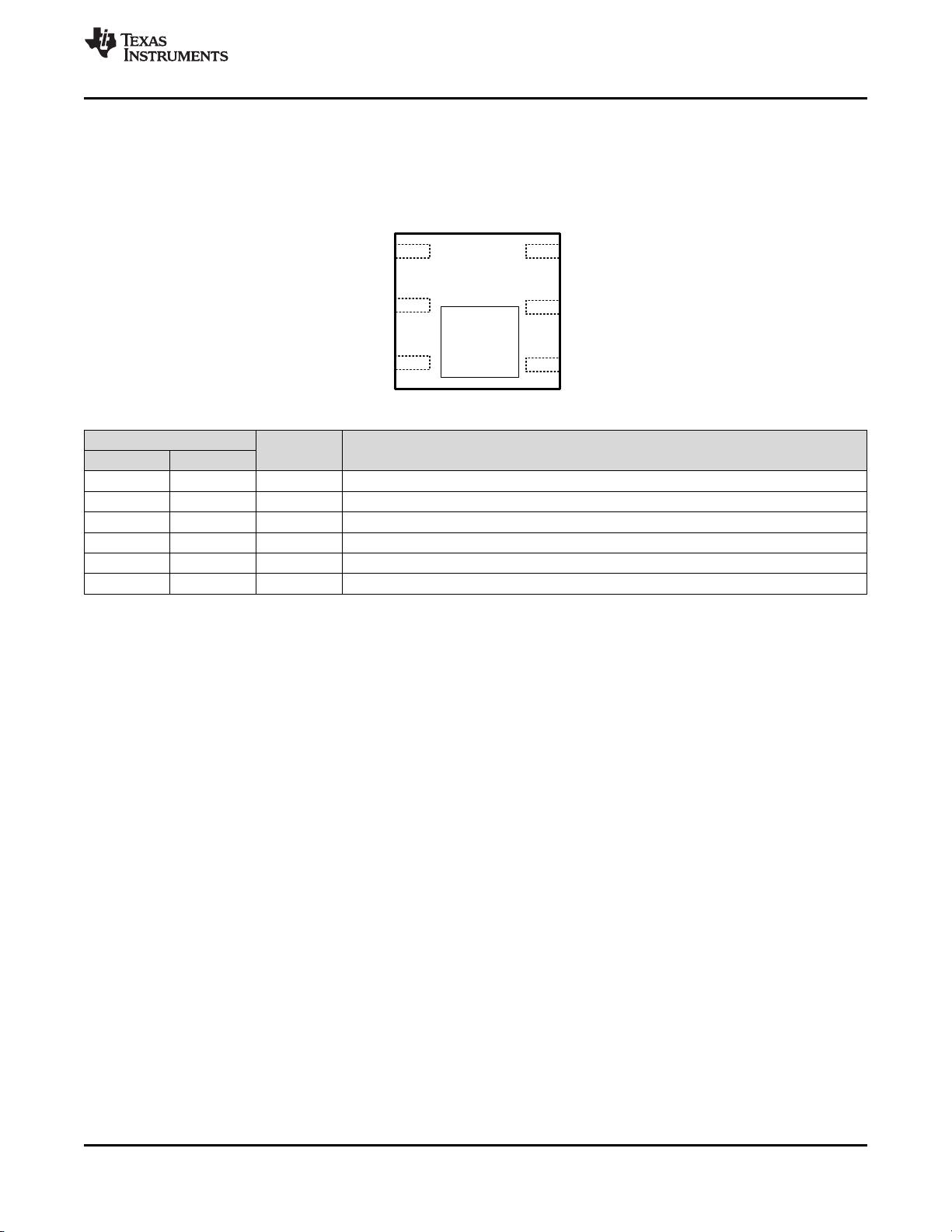
Top View
1
SDA
2
GND
NC
3
NC
4
VDD
5
SCL
6
RH
SENSOR
3
HDC1080
www.ti.com.cn
ZHCSET2A –NOVEMBER 2015–REVISED JANUARY 2016
Copyright © 2015–2016, Texas Instruments Incorporated
(1) P=Power, G=Ground, I=Input, O=Output
6 Pin Configuration and Functions
DMB Package
6 Pin PWSON
Top View
Pin Functions
PIN
I/O TYPE
(1)
DESCRIPTION
NAME NO.
SDA 1 I/O Serial data line for I2C, open-drain; requires a pull-up resistor to VDD
GND 2 G Ground
NC 3,4 - These pins may be left floating, or connected to GND
VDD 5 P Supply Voltage
SCL 6 I Serial clock line for I2C, open-drain; requires a pull-up resistor to VDD
DAP DAP - Die Attach Pad. Should be left floating. (On bottom of the device, not shown in the figure)

4
HDC1080
ZHCSET2A –NOVEMBER 2015–REVISED JANUARY 2016
www.ti.com.cn
Copyright © 2015–2016, Texas Instruments Incorporated
(1) Stresses beyond those listed under Absolute Maximum Ratings may cause permanent damage to the device. These are stress ratings
only, which do not imply functional operation of the device at these or any other conditions beyond those indicated under Recommended
Operating Conditions. Exposure to absolute-maximum-rated conditions for extended periods may affect device reliability.
7 Specifications
7.1 Absolute Maximum Ratings
(1)
MIN MAX UNIT
Input Voltage
VDD -0.3 6
VSCL -0.3 6
SDA -0.3 6
Storage Temperature T
STG
-65 150 °C
(1) JEDEC document JEP155 states that 500-V HBM allows safe manufacturing with a standard ESD control process.
(2) JEDEC document JEP157 states that 250-V CDM allows safe manufacturing with a standard ESD control process.
7.2 ESD Ratings
VALUE UNIT
V
(ESD)
Electrostatic discharge
Human-body model (HBM), per ANSI/ESDA/JEDEC JS-001
(1)
±2000
V
Charged-device model (CDM), per JEDEC specification JESD22-
C101
(2)
±500
(1) See Figure 2.
7.3 Recommended Operating Conditions
over operating range (unless otherwise noted)
MIN NOM MAX UNIT
V
DD
Supply Voltage 2.7 3 5.5 V
T
A
, Temperature sensor Ambient Operating Temperature -40 125 °C
T
A
, Humidity sensor
(1)
Ambient Operating Temperature -20 70 °C
T
A
, Humidity sensor
(1)
Functional Operating Temperature -20 85 °C
(1) For more information about traditional and new thermal metrics, see the Semiconductor and IC Package Thermal Metrics application
report, SPRA953.
7.4 Thermal Information
THERMAL METRIC
(1)
HDC1080
UNITPWSON (DMB)
6 PINS
R
θJA
Junction-to-ambient thermal resistance 49.4 °C/W
R
θJC(top)
Junction-to-case (top) thermal resistance 29.8 °C/W
R
θJB
Junction-to-board thermal resistance 23.1 °C/W
ψ
JT
Junction-to-top characterization parameter 3.3 °C/W
ψ
JB
Junction-to-board characterization parameter 23.1 °C/W
R
θJC(bot)
Junction-to-case (bottom) thermal resistance 4.2 °C/W

5
HDC1080
www.ti.com.cn
ZHCSET2A –NOVEMBER 2015–REVISED JANUARY 2016
Copyright © 2015–2016, Texas Instruments Incorporated
(1) Electrical Characteristics Table values apply only for factory testing conditions at the temperature indicated. Factory testing conditions
result in very limited self-heating of the device such that TJ = TA. No guarantee of parametric performance is indicated in the electrical
tables under conditions of internal self-heating where TJ > TA. Absolute Maximum Ratings indicate junction temperature limits beyond
which the device may be permanently degraded, either mechanically or electrically.
(2) Register values are represented as either binary (b is the prefix to the digits), or hexadecimal (0x is the prefix to the digits). Decimal
values have no prefix.
(3) Limits are ensured by testing, design, or statistical analysis at 30°C. Limits over the operating temperature range are ensured through
correlations using statistical quality control (SQC) method.
(4) Typical values represent the most likely parametric norm as determined at the time of characterization. Actual typical values may vary
over time and will also depend on the application and configuration. The typical values are not tested and are not guaranteed on
shipped production material.
(5) I
2
C read/write communication and pull-up resistors current through SCL and SDA not included.
(6) Average current consumption while conversion is in progress.
(7) This parameter is specified by design and/or characterization and it is not tested in production.
(8) The hysteresis value is the difference between an RH measurement in a rising and falling RH environment, at a specific RH point.
(9) Actual response times will vary dependent on system thermal mass and air-flow.
(10) Time for the RH output to change by 63% of the total RH change after a step change in environmental humidity.
(11) Recommended humidity operating range is 10% to 70% RH. Prolonged operation outside this range may result in a measurement
offset. The measurement offset will decrease after operating the sensor in this recommended operating range.
(12) Drift due to aging effects at typical conditions (30°C and 20% to 50% RH). This value may be impacted by dust, vaporized solvents, out-
gassing tapes, adhesives, packaging materials, etc.
7.5 Electrical Characteristics
(1)
The electrical ratings specified in this section apply to all specifications in this document, unless otherwise noted. T
A
= 30°C,
RH = 40%, and V
DD
= 3V.
PARAMETER TEST CONDITION
(2)
MIN
(3)
TYP
(4)
MAX
(3)
UNIT
POWER CONSUMPTION
I
DD
Supply Current RH measurement, bit 12 of 0x02 register =
0
(5)
190 220 µA
Temperature measurement, bit 12 of 0x02
register = 0
(5)
160 185 µA
Sleep Mode 100 200 nA
Average @ 1 measurement/second, RH (11
bit), bit 12 of 0x02 register = 0
(5)(6)
710 nA
Average @ 1 measurement/second, Temp
(11 bit), bit 12 of 0x02 register = 0
(5)(6)
590 nA
Average @ 1 measurement/second, RH
(11bit) +temperature (11 bit), bit 12 of 0x02
register = 1
(5)(6)
1.3 µA
Startup (average on Start-up time) 300 µA
I
HEAT
Heater Current
(7)
Peak current 7.2 mA
Average @ 1 measurement/second, RH
(11bit) +temperature (11 bit), bit 12 of 0x02
register = 1
(5)(6)
50 µA
RELATIVE HUMIDITY SENSOR
RH
ACC
Accuracy Refer to Figure 2 in Typical Characteristics
section.
±2 %RH
RH
REP
Repeatability
(7)
14 bit resolution ±0.1 %RH
RH
HYS
Hysteresis
(8)
10% ≤ RH ≤ 70% ±1 %RH
RH
RT
Response Time
(9)
t
63
%
(10)
15 s
RH
CT
Conversion Time
(7)
8 bit resolution 2.50 ms
11 bit resolution 3.85 ms
14 bit resolution 6.50 ms
RH
OR
Operating Range
(11)
Non-condensing 0 100 %RH
RH
LTD
Long Term Drift
(12)
±0.25 %RH/yr
TEMPERATURE SENSOR
TEMP
ACC
Accuracy
(7)
5°C < T
A
< 60°C ±0.2 ±0.4 °C
TEMP
REP
Repeatability
(7)
14 bit resolution ±0.1 °C
TEMP
CT
Conversion Time
(7)
11 bit accuracy 3.65 ms
14 bit accuracy 6.35 ms


