没有合适的资源?快使用搜索试试~ 我知道了~
avr单片机pc键盘源代码
5星 · 超过95%的资源 需积分: 13 11 下载量 200 浏览量
2008-12-22
21:29:31
上传
评论
收藏 92KB PDF 举报
温馨提示
试读
13页
avr单片机pc键盘源代码,里面详细的描述了具体代码的含义,好东西哦:)
资源推荐
资源详情
资源评论
1
AVR313: Interfacing the PC AT Keyboard
Features
• Interfacing Standard PC AT Keyboards
• Requires Only Two I/O Pins. One of them must be an External Interrupt Pin
• No Extra Hardware Required
• Complete Example in C, Implementing a Keyboard to Serial Converter
Introduction
Most microcontrollers requires some kind of a human interface. This application note
describes one way of doing this using a standard PC AT keyboard.
The Physical Interface
The physical interface between the keyboard and the host is shown in Figure 1. Two
signal lines are used, clock and data. The signal lines are open connector, with pullup
resistors located in the keyboard. This allows either the keyboard or the host system
to force a line to low level. Two connector types are available, the 5-pin DIN connector
of “5D” type, and the smaller six-pin mini-DIN. The pin assignments are shown in
Table 1.
Figure 1. The Interface.
Keyboard
+5V
Clock
Data
GND
AV
R
V
cc
VCC
GND
INT0
(or INT1)
P
xy
8-bit
Microcontroller
Application
Note
Rev. 1235B–AVR–05/02
2
AVR313
1235B–AVR–05/02
Timing The timing for the data transferred from the keyboard to the host is shown in Figure 2.
The protocol is: one start bit (always 0), eight data bits, one odd parity bit and one stop
bit (always 1). The data is valid during the low period of the clock pulse. The keyboard is
generating the clock signal, and the clock pulses are typically 30-50 µs low and 30-50 µs
high.
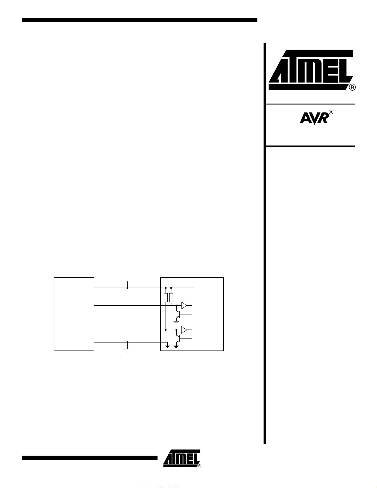
The host system can send commands to the keyboard by forcing the clock line low. It
then pulls the data line low (the start bit). Now, the clock line must be released. The key-
board will count 10 clock pulses. The data line must be set up to the right level by the
host before the trailing edge of the clock pulse. After the tenth bit, the keyboard checks
for a high level on the data line (the stop bit), and if it is high, it forces it low. This tells the
host that the data is received by the keyboard. The software in this design note will not
send any commands to the keyboard.
Scan Codes TheATkeyboardhasascancodeassociatedwitheachkey.Whenakeyispressed,
this code is transmitted. If a key is held down for a while, it starts repeating. The repeat
rate is typically 10 per second. When a key is released, a “break” code ($F0) is transmit-
ted followed by the key scan code. For most of the keys, the scan code is one byte.
Some keys like the
Home
,
Insert
and
Delete
keys have an extended scan code, from
twotofivebytes.Thefirstbyteisalways$E0.Thisisalsotrueforthe“break” sequence,
e.g., E0 F0 xx…
AT keyboards are capable of handling three sets of scan codes, where set two is
default. This example will only use set two.
The Software The code supplied with this application note is a simple keyboard to RS-232 interface.
The scan codes received from the keyboard are translated into appropriate ASCII char-
acters and transmitted by the UART. The source code is written in C, and is easily
modified and adaptable to all AVR microconrollers with SRAM.
Note: The linkerfile (AVR313.xcl) included in the software archive has to be included instead of
the standard linkerfile. This is done from the include menu under XLINK – Options. The
linker file applies to AT90S8515 only.
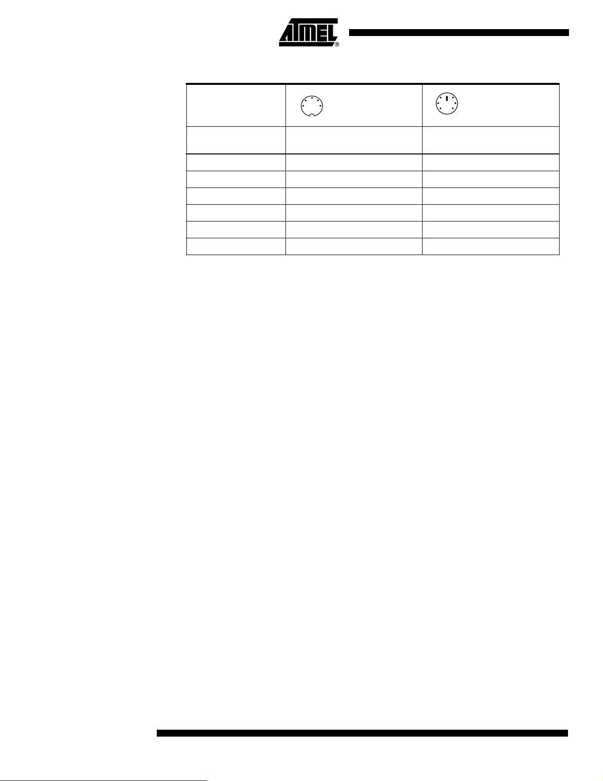
Table 1. AT Keyboard Connector Pin Assignments
AT Computer
Signals
DIN41524, Female at
Computer, 5-pin DIN 180
o
6-pin Mini DIN PS2 Style
Female at Computer
Clock 1 5
Data 2 1
nc 3 2,6
GND 4 3
+5V 5 4
Shield Shell Shell
1
2
3
45
4
2
3
65
1
3
AVR313
1235B–AVR–05/02
The Algorithm Keyboard reception is handled by the interrupt function INT0_interrupt.Thereception
will operate independent of the rest of the program.
The algorithm is quite simple: Store the value of the data line at the leading edge of the
clock pulse. This is easily handled if the clock line is connected to the INT0 or INT1 pin.
The interrupt function will be executed at every edge of the clock cycle, and data will be
stored at the falling edge. After all bits are received, the data can be decoded. This is
done by calling the decode function. For character keys, this function will store an ASCII
character in a buffer. It will take into account if the shift key is held down when a key is
pressed. Other keys like function keys, navigation keys (arrow keys, page up/down keys
etc.) and modifier keys like Ctrl and Alt are ignored.
The mapping from scan codes to ascii characters are handled with table look-ups, one
table for shifted characters and one for un-shifted.
Modifications and
Improvements
If the host falls out of sync with the keyboard, all subsequent data received will be
wrong. One way to solve this is to use a time out. If 11 bits are not received within
1.5 ms, some error have occurred. The bit counter should be reset and the faulty data
discarded.
If keyboard parameters like typematic rate and delay are to be set, data must be sent to
the keyboard. This can be done as described earlier. For the commands, see the key-
board manufacturer’s specifications.
Figure 2. Timing for Keyboard to Host Transfer
Main.c #include <pgmspace.h>
#include <stdio.h>
#include <stdlib.h>
#include "io8515.h"
#include "serial.h"
#include "gpr.h"
#include "kb.h"
void main(void)
{
unsigned char key;
init_uart(); // Initializes the UART transmit buffer
init_kb(); // Initialize keyboard reception
while(1)
{
key=getchar();
putchar(key);
delay(100);
}
}
Bit 0 Bit 1 Bit 2 Bit 3 Bit 4 Bit 5 Bit 6 Bit 7
Parity
Stop
Start
Clock
Data
剩余12页未读,继续阅读
资源评论
- 筱菂2013-06-15能用,资料不详细
- xjoxjo12012-07-20能用,资料不详细
- wanffee2018-12-01引用的头文件哪里找?
athlan2000
- 粉丝: 6
- 资源: 12
上传资源 快速赚钱
- 我的内容管理 展开
- 我的资源 快来上传第一个资源
- 我的收益 登录查看自己的收益
- 我的积分 登录查看自己的积分
- 我的C币 登录后查看C币余额
- 我的收藏
- 我的下载
- 下载帮助
安全验证
文档复制为VIP权益,开通VIP直接复制
信息提交成功