LM2731开关稳压器电流升压转换器SOT-23封装
需积分: 2 23 浏览量
2024-04-11
13:57:18
上传
评论
收藏 433KB PDF 举报


July 2007
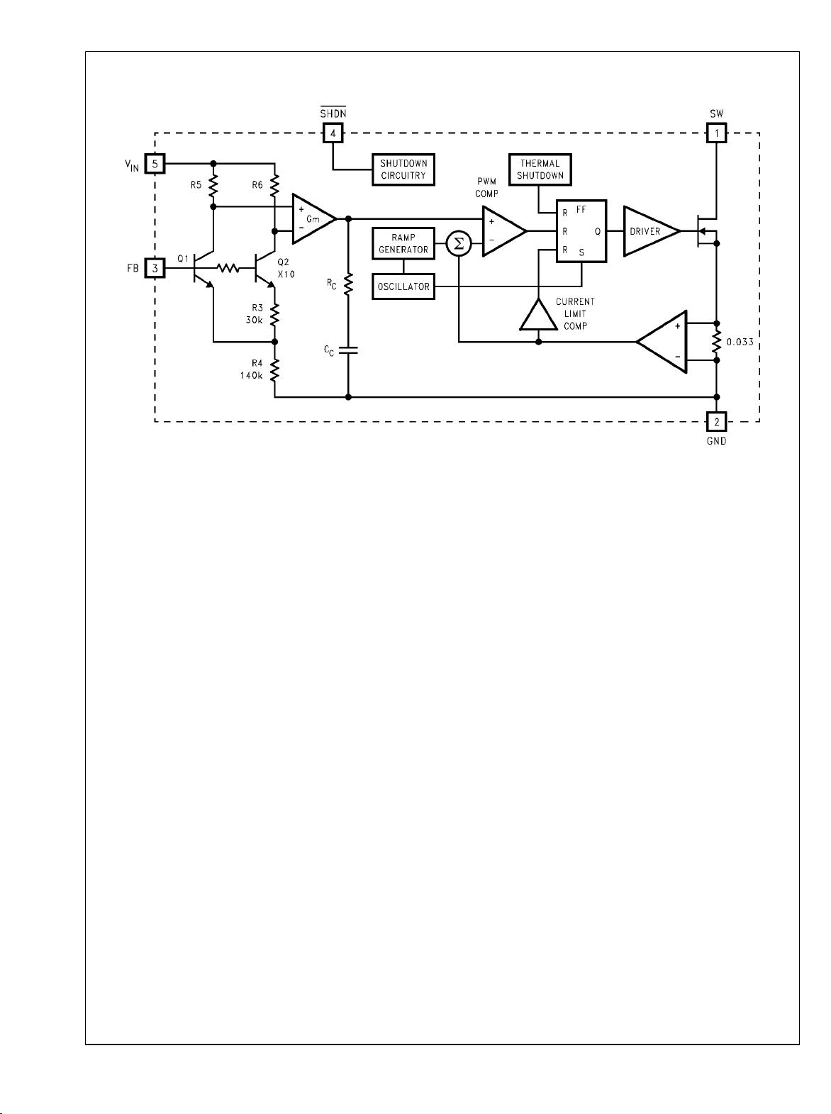
LM2731
0.6/1.6 MHz Boost Converters With 22V Internal FET Switch
in SOT-23
General Description
The LM2731 switching regulators are current-mode boost
converters operating at fixed frequencies of 1.6 MHz (“X” op-
tion) and 600 kHz (“Y” option).
The use of SOT-23 package, made possible by the minimal
power loss of the internal 1.8A switch, and use of small in-
ductors and capacitors result in the industry's highest power
density. The 22V internal switch makes these solutions per-
fect for boosting to voltages up to 20V.
These parts have a logic-level shutdown pin that can be used
to reduce quiescent current and extend battery life.
Protection is provided through cycle-by-cycle current limiting
and thermal shutdown. Internal compensation simplifies de-
sign and reduces component count.
Switch Frequency
X Y
1.6 MHz 0.6 MHz
Features
■
22V DMOS FET switch
■
1.6 MHz (“X”), 0.6 MHz (“Y”) switching frequency
■
Low R
DS
(ON) DMOS FET
■
Switch current up to 1.8A
■
Wide input voltage range (2.7V–14V)
■
Low shutdown current (<1 µA)
■
5-Lead SOT-23 package
■
Uses tiny capacitors and inductors
■
Cycle-by-cycle current limiting
■
Internally compensated
Applications
■
White LED Current Source
■
PDA’s and Palm-Top Computers
■
Digital Cameras
■
Portable Phones and Games
■
Local Boost Regulator
Typical Application Circuit
20059110
20059130
© 2007 National Semiconductor Corporation 200591 www.national.com
LM2731 0.6/1.6 MHz Boost Converters With 22V Internal FET Switch in SOT-23


剩余15页未读,继续阅读
资源评论


