


State Machine Coding Styles for Synthesis
Clifford E. Cummings
Sunburst Design, Inc.
ABSTRACT
This paper details efficient Verilog coding styles to infer synthesizable state machines. HDL
considerations such as advantages and disadvantages of one-always block FSMs Vs. two-always
block FSMs are described.
SNUG 1998 State Machine Coding Styles for Synthesis
Rev 1.1
2
Introduction
Steve Golson's 1994 paper, "State Machine Design Techniques for Verilog and VHDL" [1], is a
great paper on state machine design using Verilog, VHDL and Synopsys tools. Steve's paper also
offers in-depth background concerning the origin of specific state machine types.
This paper, "State Machine Coding Styles for Synthesis," details additional insights into state
machine design including coding style approaches and a few additional tricks.
State Machine Classification
There are two types of state machines as classified by the types of outputs generated from each.
The first is the Moore State Machine where the outputs are only a function of the present state,
the second is the Mealy State Machine where one or more of the outputs are a function of the
present state and one or more of the inputs.
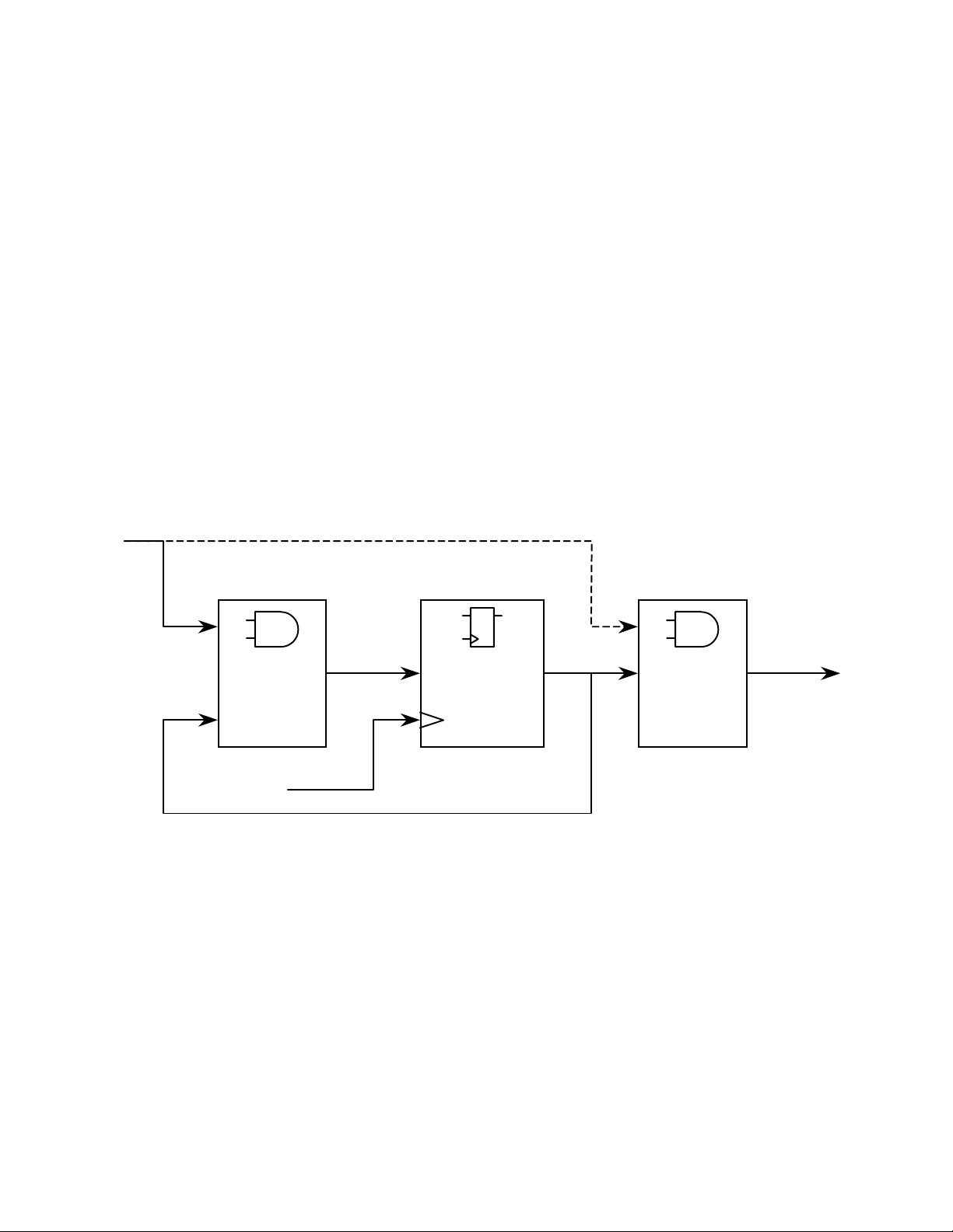
Figure 1 - FSM Block Diagram
In addition to classifying state machines by their respective output-generation type, state
machines are also often classified by the state encoding employed by each state machine. Some
of the more common state encoding styles include [1] [2] [3]: highly-encoded binary (or binary-
sequential), gray-code, Johnson, one-hot, almost one-hot and one-hot with zero-idle (note: in the
absence of a known official designation for the last encoding-style listed, the author selected the
"one-hot with zero-idle" title. A more generally accepted name may exist).
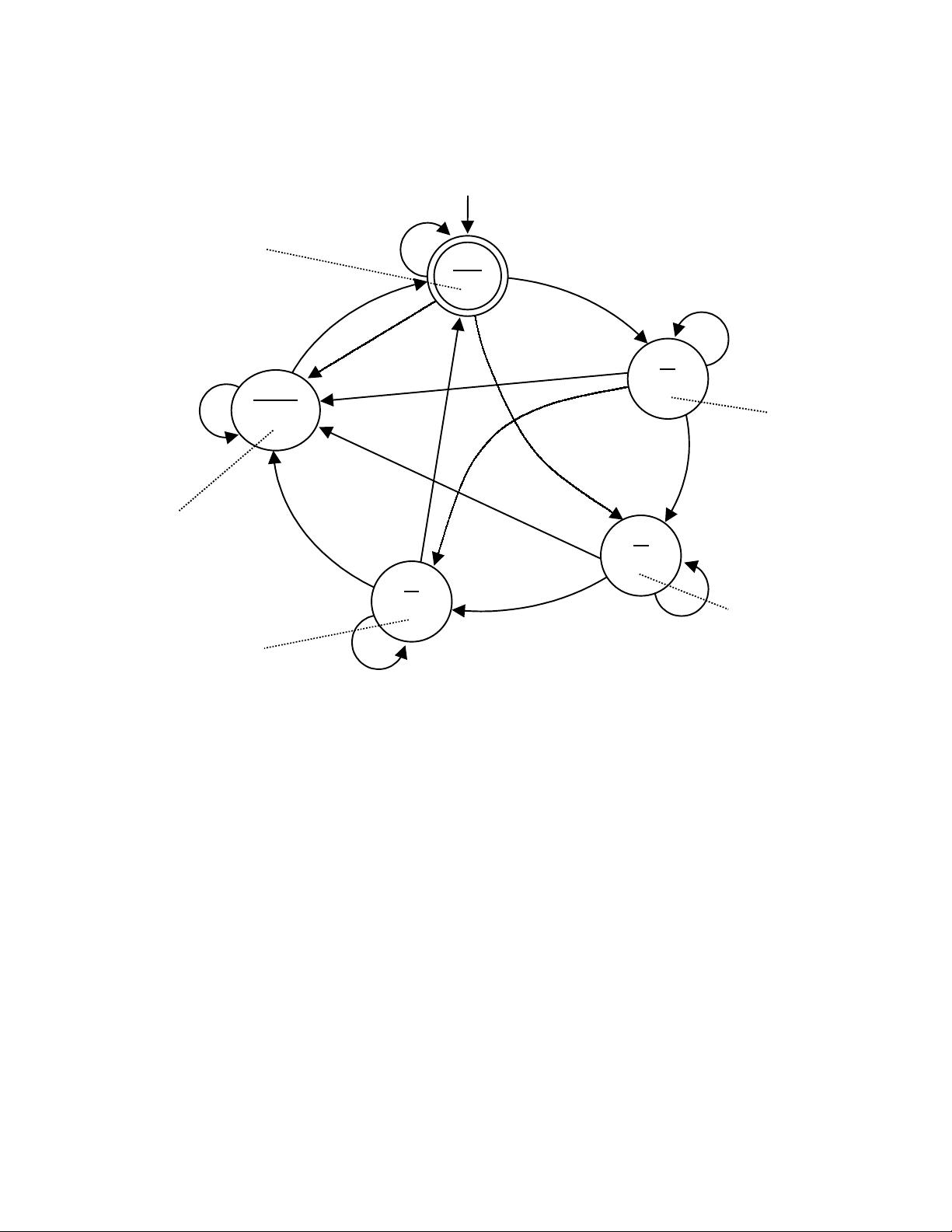
Using the Moore FSM state diagram shown in Figure 2, this paper will detail synthesizable
Verilog coding styles for highly-encoded binary, one-hot and one-hot with zero-idle state
machines. This paper also details usage of the Synopsys FSM Tool to generate binary, gray and
one-hot state machines. Coded examples of the three coding styles for the state machine in Figure
Present
State
FF’s
Next
State
Logic
Output
Logic
next
state
clock
inputs
outputs
combinational
logic
combinational
logic
sequential
logic
state
(Mealy State Machine Only)
SNUG 1998 State Machine Coding Styles for Synthesis
Rev 1.1
3
2, plus an example with the correct Synopsys FSM Tool comments, have been included at the
end of this paper.
Figure 2 - Benchmark 1 (bm1) State Diagram
FSM Verilog Modules
Guideline: make each state machine a separate Verilog module.
Keeping each state machine separate from other synthesized logic simplifies the tasks of state
machine definition, modification and debug. There are also a number of EDA tools that assist in
the design and documentation of FSMs, but in general they only work well if the FSM is not
mingled with other logic-code.
State Assignments
Guideline: make state assignments using parameters with symbolic state names.
Defining and using symbolic state names makes the Verilog code more readable and eases the
task of redefining states if necessary. Examples 1-3 show binary, one-hot and one-hot with zero-
idle parameter definitions for the FSM state diagram in Figure 2.
n_o1 = 1
o2 = 0
o3 = 0
o4 = 0
err = 0
i
1 * i2
__
i
1 * i2 * i3
i2 * i3
__
i
2 * i3 * i4
_
_
i
3 * i4
_
_ __
i
3 * i4
__
i1
__ __
i
2 * i3 * i4
__ __
i1 * i2 * i3
n_o1 = 1
o2 = 0
o3 = 0
o4 = 0
err = 1
n_o1 = 1
o2 = 0
o3 = 0
o4 = 1
err = 0
n_o1 = 1
o2 = 1
o3 = 1
o4 = 0
err = 0
n
_o1 = 0
o
2 = 1
o
3 = 0
o
4 = 0
e
rr = 0
_
___
n
rst
__
i1
IDLE
IDLE
i1
ERROR
__
i
1 * i2
S3
i
3
S2
__
i2
S1
i1 * i2
__
i1

SNUG 1998 State Machine Coding Styles for Synthesis
Rev 1.1
4
parameter [2:0] // synopsys enum code
IDLE = 3'd0,
S1 = 3'd1,
S2 = 3'd2,
S3 = 3'd3,
ERROR = 3'd4;
Example 1 - Parameter definitions for binary encoding
parameter [4:0] IDLE = 5'b00001,
S1 = 5'b00010,
S2 = 5'b00100,
S3 = 5'b01000,
ERROR = 5'b10000;
Example 2 - Parameter definitions for verbose one-hot encoding
parameter [4:0] IDLE = 5'd0,
S1 = 5'd1,
S2 = 5'd2,
S3 = 5'd3,
ERROR = 5'd4;
Example 3 - Parameter definitions for simplified one-hot encoding
The simplified one-hot encoding shown Example 3 uses decimal numbers to index into the state
register. This technique permits comparison of single bits as opposed to comparing against the
entire state vector using the full state parameters shown in Example 2.
parameter [4:1] // ERROR is 4'b0000
IDLE = 4'd1,
S1 = 4'd2,
S2 = 4'd3,
S3 = 4'd4;
Example 4 - Parameter definitions for one-hot with zero-idle encoding
The one-hot with zero-idle encoding can yield very efficient FSMs for state machines that have
many interconnections with complex equations, including a large number of connections to one
particular state. Frequently, multiple transitions are made either to an IDLE state or to another
common state (such as the ERROR-state in this example).
One could also define symbolic state names using the macro-definition compiler directives
(`define), but `define creates a global definition (from the point where the definition is read in the
Verilog-code input stream). Unlike `define constants, parameters are constants local to the
module where they are declared, which allows a design to have multiple FSMs with duplicate
state names, such as IDLE or READ, each with a unique state encoding.
Occasionally, FSM code is written with parameter-defined state definitions, but subsequent code
still includes explicit binary state encodings elsewhere in the module. This defeats the purpose of
using symbolically labeled parameters. Only use the pre-defined parameter names for state
testing and next-state assignment.
Additional notes on experimenting with different state definitions using Synopsys generated
binary, gray and one-hot encodings are detailed in the section, "Synopsys FSM Tool."

SNUG 1998 State Machine Coding Styles for Synthesis
Rev 1.1
5
Two-Always Block State Machine
A synthesizable state machine may be coded many ways. Two of the most common, easily
understood and efficient methods are two-always block and one-always block state machines.
The easiest method to understand and implement is the two-always block state machine with
output assignments included in either the combinational next-state always block or separate
continuous-assignment outputs. This method partitions the Verilog code into the major FSM
blocks shown in Figure 1: clocked present state logic, next state combinational logic and output
combinational logic.
Sequential Always Block
Guideline: only use Verilog nonblocking assignments in the sequential always block.
Guideline: only use Verilog nonblocking assignments in all always blocks used to generate
sequential logic.
For additional information concerning nonblocking assignments, see reference [4].
Verilog nonblocking assignments mimic the pipelined register behavior of actual hardware and
eliminate many potential Verilog race conditions. Many engineers make nonblocking
assignments using an intra-assignment timing delay (as shown in Example 5). There are two
good reasons and one bad reason for using intra-assignment timing delays with nonblocking
assignments.
Good reasons: (1) gives the appearance of a clk->q delay on a clocked register (as seen using a
waveform viewer); (2) helps avoid hold-time problems when driving most gate-level
models from an RTL model.
Bad reason: "we add delays because Verilog nonblocking assignments are broken!" - This is not
true.
When implementing either a binary encoded or a verbose one-hot encoded FSM, on reset the
state register will be assigned the IDLE state (or equivalent) (Example 5).
always @(posedge clk or posedge rst)
if (rst) state <= #1 IDLE;
else state <= #1 next;
Example 5 - Sequential always block for binary and verbose one-hot encoding
When implementing a simplified one-hot encoded FSM, on reset the state register will be
assigned all zeros followed immediately by reassigning the IDLE bit of the state register
(Example 6). Note, there are two nonblocking assignments assigning values to the same bit. This
is completely defined by the IEEE Verilog Standard [5] and in this case, the last nonblocking
assignment supercedes any previous nonblocking assignment (updating the IDLE bit of the state
register).


