


GigaDevice Semiconductor Inc.
GD32103E-EVAL Evaluation Board
User Manual

User Manual
GD32103E-EVAL
1 / 14
Table of Contents
List of Figures ............................................................................................................................. 2
1 Introduction ...................................................................................................................... 3
2 Function pin assignment ................................................................................................ 3
3 Getting started ................................................................................................................. 5
4 Hardware layout overview .............................................................................................. 5
4.1 Power supply ....................................................................................................................................... 5
4.2 Boot option ........................................................................................................................................... 5
4.3 LED ....................................................................................................................................................... 6
4.4 Key ........................................................................................................................................................ 6
4.5 USART1/USART2 ............................................................................................................................... 7
4.6 ADC/DAC ............................................................................................................................................. 7
4.7 I2S ......................................................................................................................................................... 8
4.8 I2C ......................................................................................................................................................... 8
4.9 SPI-Serial Flash .................................................................................................................................. 9
4.10 SDIO ..................................................................................................................................................... 9
4.11 USB ..................................................................................................................................................... 10
4.12 CAN ..................................................................................................................................................... 10
4.13 RTC ..................................................................................................................................................... 10
4.14 EXMC-LCD ........................................................................................................................................ 11
4.15 EXMC-NAND Flash .......................................................................................................................... 12
4.16 Extension............................................................................................................................................ 12
5 Revision history ............................................................................................................. 13

User Manual
GD32103E-EVAL
2 / 14
List of Figures
Figure 1 Schematic diagram of power supply ......................................................................................................... 5
Figure 2. Schematic diagram of boot option ............................................................................................................ 5
Figure 3. Schematic diagram of LED function ......................................................................................................... 6
Figure 4. Schematic diagram of Key function .......................................................................................................... 6
Figure 5. Schematic diagram of USART1/USART2 function ................................................................................ 7
Figure 6. Schematic diagram of ADC/DAC function ............................................................................................... 7
Figure 7. Schematic diagram of I2S function ........................................................................................................... 8
Figure 8. Schematic diagram of I2C function .......................................................................................................... 8
Figure 9. Schematic diagram of SPI-Serial Flash function .................................................................................... 9
Figure 10. Schematic diagram of SDIO function ..................................................................................................... 9
Figure 11. Schematic diagram of USB function .................................................................................................... 10
Figure 12. Schematic diagram of CAN function .................................................................................................... 10
Figure 13. Schematic diagram of RTC function .................................................................................................... 10
Figure 14. Schematic diagram of EXMC-LCD function ........................................................................................ 11
Figure 15. Schematic diagram of EXMC-NAND Flash function ......................................................................... 12
Figure 16. Schematic diagram of Extension Pin ................................................................................................... 12
User Manual
GD32103E-EVAL
3 / 14
1 Introduction
GD32103E-EVAL evaluation board uses GD32F103ZET6 as the main controller. As a
complete development platform of GD32F103xx powered by ARM® Cortex™-M3 core, the
board supports full range of peripherals. It uses Mini USB interface or AC/DC adapter as 5V
power supply. JTAG, Reset, Boot, User button key, LED, CAN, I2C, I2S, USART, SDIO, RTC,
EXMC, SPI, USB, ADC, DAC and Extension Pin are also included. This document details its
hardware schematic and the relevant applications.
2 Function pin assignment
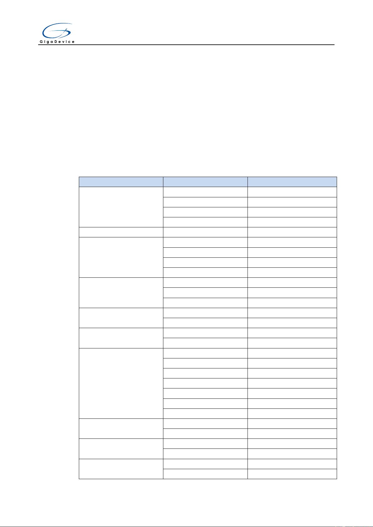
Table 1. Pin assignment
Function Pin Description
LED
PF0 LED2
PF1 LED3
PF2 LED4
PF3 LED5
RESET K1-Reset
KEY
PA0 K2-Wakeup
PC13 K3-Temper
PF5 K4-User Key1
PF4 K5-User Key2
USB
PA11 USBDM
PA12 USBDP
PG8 USBDP pull up pin
CAN
PD0 CAN_RX
PD1 CAN_TX
I2C
PB6 I2C1_SCL
PB7 I2C1_SDA
I2S
PB12 I2S2_WS
PB13 I2S2_CK
PB15 I2S2_DIN
PA4 MSEL
PA5 MCLK
PA7 MDIN
PC6 I2S2_MCK
USART1
PA9 USART1_TX
PA10 USART1_RX
USART2
PA2 USART2_TX
PA3 USART2_RX
SDIO
PC8 SDIO_DAT0
PC9 SDIO_DAT1
User Manual
GD32103E-EVAL
4 / 14
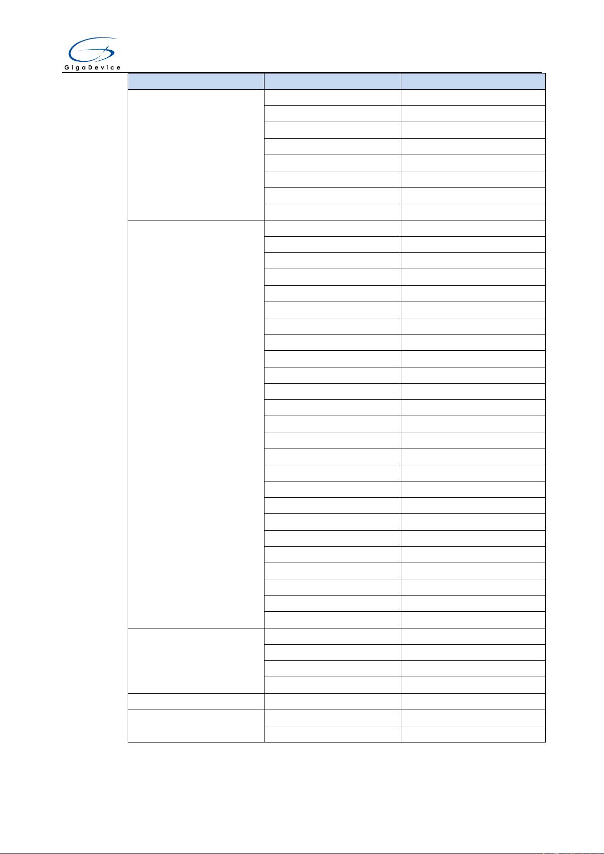
Function Pin Description
PC10 SDIO_DAT2
PC11 SDIO_DAT3
PB8 SDIO_DAT4
PB9 SDIO_DAT5
PC6 SDIO_DAT6
PC7 SDIO_DAT7
PD2 SDIO_CMD
PC12 SDIO_CLK
EXMC
PD14 EXMC_D0
PD15 EXMC_D1
PD0 EXMC_D2
PD1 EXMC_D3
PE7 EXMC_D4
PE8 EXMC_D5
PE9 EXMC_D6
PE10 EXMC_D7
PE11 EXMC_D8
PE12 EXMC_D9
PE13 EXMC_D10
PE14 EXMC_D11
PE15 EXMC_D12
PD8 EXMC_D13
PD9 EXMC_D14
PD10 EXMC_D15
PD11 EXMC_A16
PD12 EXMC_A17
PE2 EXMC_A23
PD4 EXMC_NOE
PD5 EXMC_NWE
PD6 EXMC_NWAIT
PD7 EXMC_NCE2
PG6 EXMC_INT2
PG9 EXMC_NE2
SPI
PA5 SPI1_SCK
PA6 SPI1_MISO
PA7 SPI1_MOSI
PE3 SPI Flash_CS
ADC PC3
ADC123c_IN13
DAC
PA4
DAC_OUT1
PA5
DAC_OUT2


