Using-PIC32-MCUs-to-Develop-GSMGPRSGPS-Solutions-Microchip
需积分: 0 26 浏览量
2017-06-26
22:39:07
上传
评论
收藏 483KB PDF 举报

© 2011 Microchip Technology Inc. DS01373A-page 1
INTRODUCTION
Technologies that allow both wireless and wired
systems to communicate with other devices of the
same ability are referred to as Machine-to-Machine
(M2M). M2M uses a device to capture an event, which
is then relayed through a network to an application that
translates the event into meaningful information. A
common application of M2M is fleet management,
where vehicle tracking is wirelessly transmitted to a
central monitoring office over cellular networks.
There are many popular M2M applications, one of
which is a utility meter. One of the major benefits of a
M2M-based utility meter over a traditional one, is
immediate operational efficiency from reading and
programming meters remotely, which eliminates the
need to physically visit the meter.
Another application becoming more popular with M2M
technology is in-car GPS navigation. With this
technology, consumers now have a complete GPS
navigation system in their vehicles. This technology
can be used to track a driver’s current location, or
provide a map for directions. Also, the consumer can
make an emergency call from the same device that is
doing the tracking. Businesses can use this technology
for parking lots to know how long a vehicle has been
parked and to charge it accordingly.
The Microchip M2M PICtail™ Plus Daughter Board
(referred to as the M2M Board) developed by u-blox
AG, was designed to connect directly to the PICtail™
interface of the Multimedia Expansion Board (MEB),
but can also be used with any PIC32 microcontroller.
This application note describes a reference design that
enables the implementation of GSM/GPRS/GPS
connectivity using a PIC32 microcontroller (MCU), the
M2M Board, and the MEB.
Feature Overview
The M2M PICtail Plus Daughter Board contains many
features, including GSM, GPRS, and GPS.
• Global System for Mobile Communication (GSM)
GSM is a popular world-wide standard for mobile
telephone systems. GSM includes technologies in
both signaling and speech channels, which are
digital; therefore, GSM is considered a Second
Generation (i.e., 2G) mobile phone system. This
facilitates the wide-spread implementation of data
communication applications into the system. GSM
also implements a Short Message Service (SMS),
called text messaging.
• General Packet Radio Service (GPRS)
GPRS is a service on 2G and 3G cellular
communication systems (GSM). GPRS provides
data rates of 56-114 kbps, which provides users
with the capability to connect to the Internet.
• Global Positioning System (GPS)
GPS is a space-based navigation system that pro-
vides reliable location and time information in all
weather conditions and at all times, and anywhere
on or near the Earth when and where there is an
unobstructed line of sight to four or more GPS sat-
ellites. It is freely accessible by anyone with a GPS
receiver.
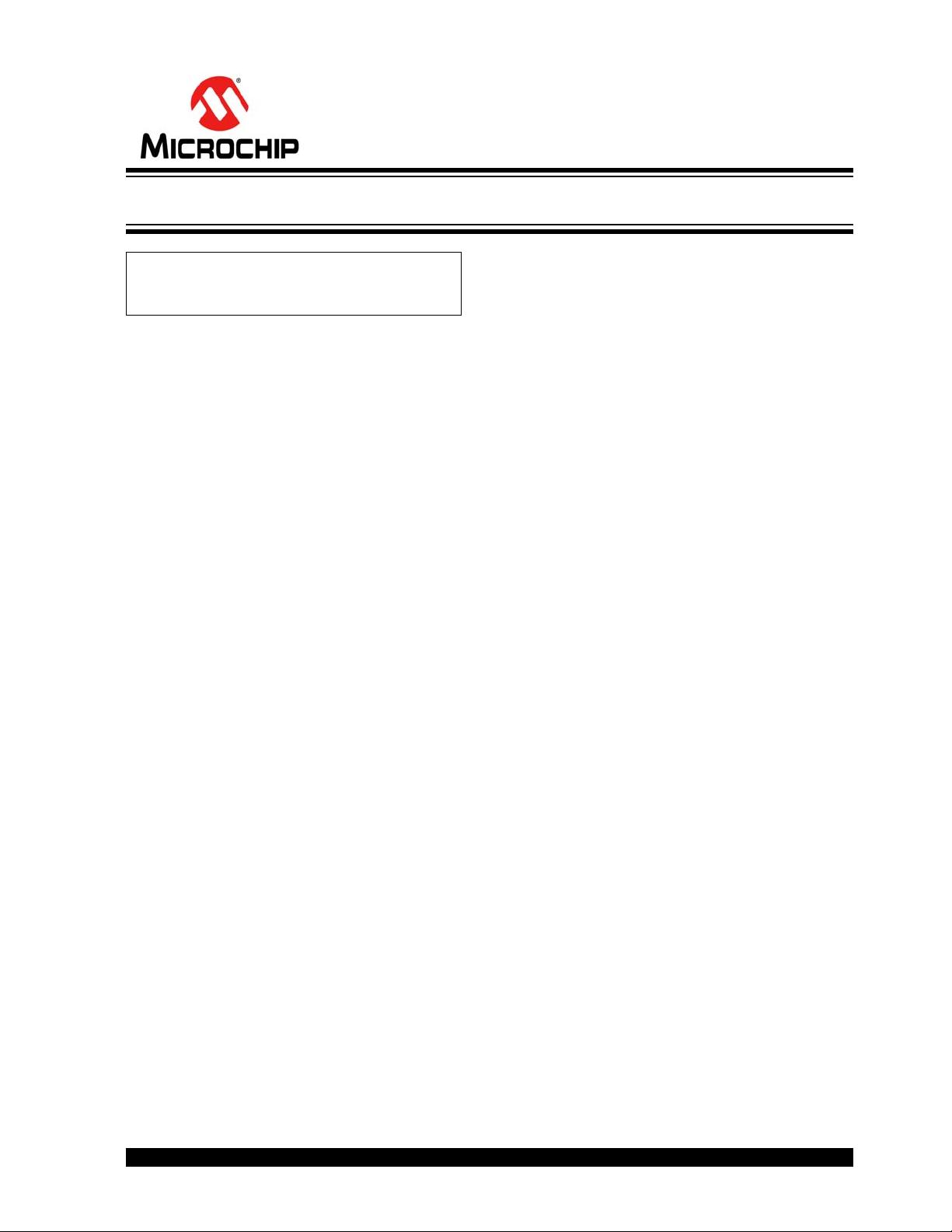
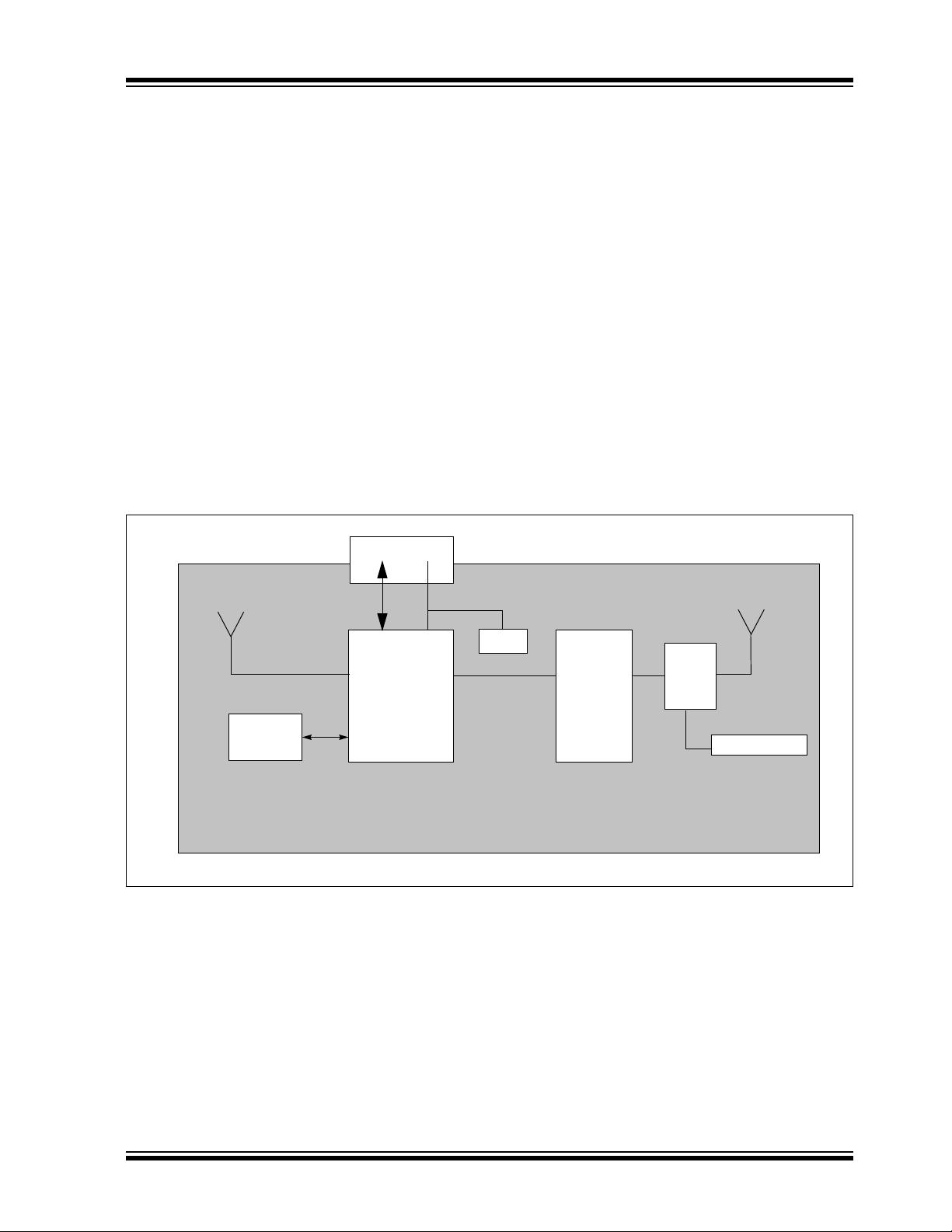
Functionality
The main functionality of the M2M Board is
accomplished using two communications modules from
u-blox A, which is a company that specializes in GSM/
GPS ICs. For more information, visit www.u-blox.com.
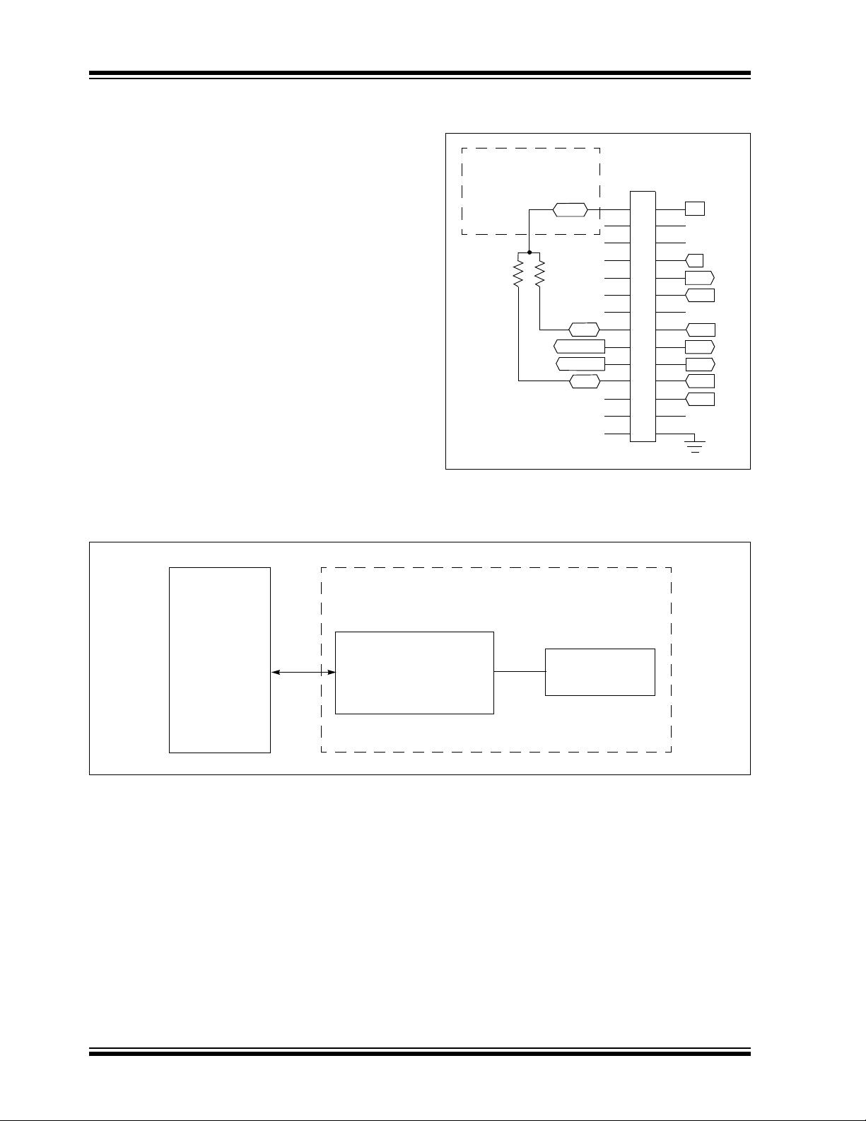
The M2M Board was designed to connect to
Microchip’s MEB. The MEB uses Microchip’s PIC32
starter kit collection as the primary controller source.
This suite makes it easy to start and implement
embedded controller projects due to its:
• Built-in debugger
• USB power source
• On-board header for easy attachment to PCBs
• PIC32 device with high-speed performance and
no peripheral loss
Authors: Adam Folts
Microchip Technology Inc.,
with contributions from u-blox AG
AN1373
Using PIC32 MCUs to Develop GSM/GPRS/GPS Solutions
剩余33页未读,继续阅读
资源评论


