没有合适的资源?快使用搜索试试~ 我知道了~
资源推荐
资源详情
资源评论
This is information on a product in full production.
November 2015 DocID14611 Rev 12 1/144
STM32F103xC, STM32F103xD,
STM32F103xE
High-density performance line ARM
®
-based 32-bit MCU with 256 to 512KB
Flash, USB, CAN, 11 timers, 3 ADCs, 13 communication interfaces
Datasheet − production data
Features
• Core: ARM
®
32-bit Cortex
®
-M3 CPU
– 72 MHz maximum frequency, 1.25 DMIPS/MHz
(Dhrystone 2.1) performance at 0 wait state
memory access
– Single-cycle multiplication and hardware
division
• Memories
– 256 to 512 Kbytes of Flash memory
– up to 64 Kbytes of SRAM
– Flexible static memory controller with 4 Chip
Select. Supports Compact Flash,
SRAM,
PSRAM, NOR and NAND
memories
– LCD parallel interface, 8080/6800 modes
• Clock, reset and supply management
– 2.0 to 3.6 V application supply and I/Os
– POR, PDR, and programmable voltage detector
(PVD)
– 4-to-16 MHz crystal oscillator
– Internal 8 MHz factory-trimmed RC
– Internal 40 kHz RC with calibration
– 32 kHz oscillator for RTC with calibration
• Low power
– Sleep, Stop and Standby modes
–V
BAT
supply for RTC and backup registers
• 3 × 12-bit, 1 µs A/D converters (up to 21
channels)
– Conversion range: 0 to 3.6 V
– Triple-sample and hold capability
– Temperature sensor
• 2 × 12-bit D/A converters
• DMA: 12-channel DMA controller
– Supported peripherals: timers, ADCs, DAC,
SDIO, I
2
Ss, SPIs, I
2
Cs and USARTs
• Debug mode
– Serial wire debug (SWD) & JTAG interfaces
–Cortex
®
-M3 Embedded Trace Macrocell™
• Up to 112 fast I/O ports
– 51/80/112 I/Os, all mappable on 16 external
interrupt vectors and almost all 5 V-tolerant
• Up to 11 timers
– Up to four 16-bit timers, each with up to 4
IC/OC/PWM or pulse counter and quadrature
(incremental) encoder input
– 2 × 16-bit motor control PWM timers with dead-
time generation and emergency stop
– 2 × watchdog timers (Independent and Window)
– SysTick timer: a 24-bit downcounter
– 2 × 16-bit basic timers to drive the DAC
• Up to 13 communication interfaces
– Up to 2 × I
2
C interfaces (SMBus/PMBus)
– Up to 5 USARTs (ISO 7816 interface, LIN, IrDA
capability, modem control)
– Up to 3 SPIs (18 Mbit/s), 2 with I
2
S interface
multiplexed
– CAN interface (2.0B Active)
– USB 2.0 full speed interface
– SDIO interface
• CRC calculation unit, 96-bit unique ID
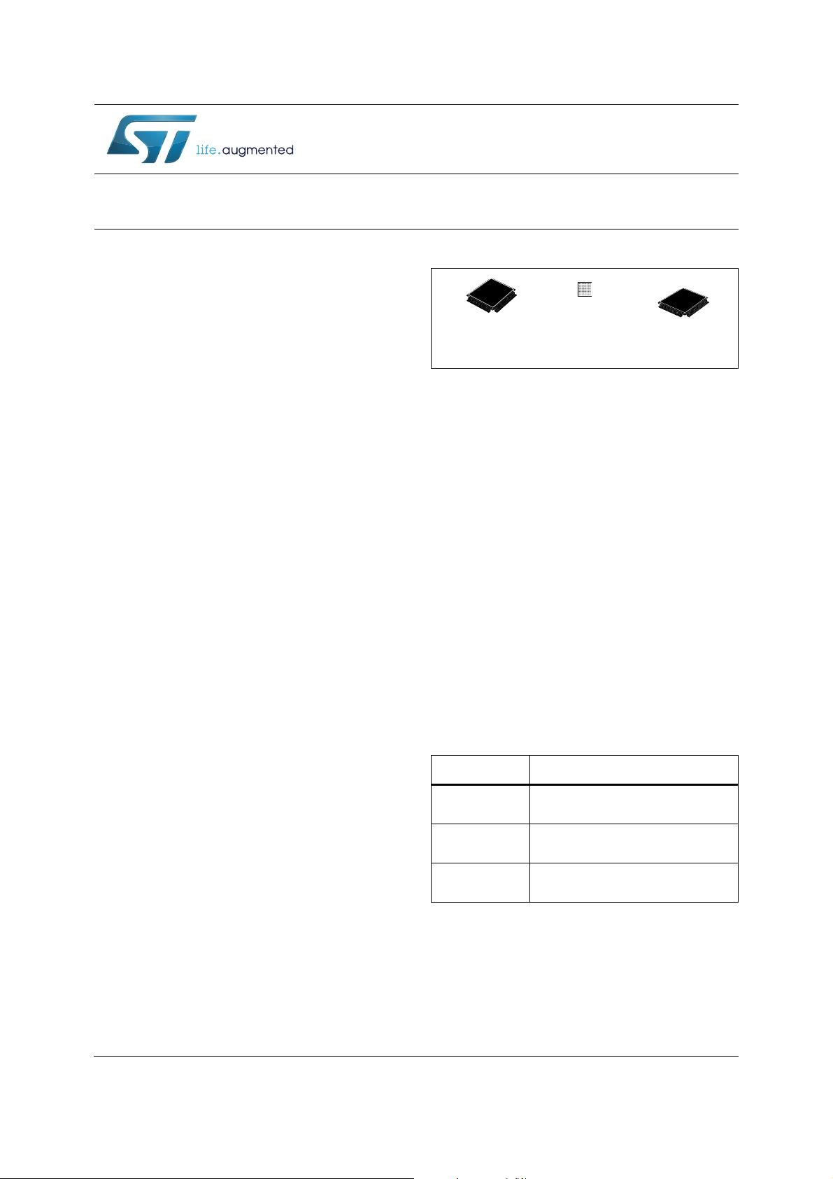
• ECOPACK
®
packages
Table 1.Device summary
Reference Part number
STM32F103xC
STM32F103RC STM32F103VC
STM32F103ZC
STM32F103xD
STM32F103RD STM32F103VD
STM32F103ZD
STM32F103xE
STM32F103RE STM32F103ZE
STM32F103VE
LQFP64 10 × 10 mm,
LQFP100 14 × 14 mm,
LQFP144 20 × 20 mm
LFBGA100 10 × 10 mm
LFBGA144 10 × 10 mm
WLCSP64
www.st.com
Contents STM32F103xC, STM32F103xD, STM32F103xE
2/144 DocID14611 Rev 12
Contents
1 Introduction . . . . . . . . . . . . . . . . . . . . . . . . . . . . . . . . . . . . . . . . . . . . . . . . 9
2 Description . . . . . . . . . . . . . . . . . . . . . . . . . . . . . . . . . . . . . . . . . . . . . . . . 10
2.1 Device overview . . . . . . . . . . . . . . . . . . . . . . . . . . . . . . . . . . . . . . . . . . . . 11
2.2 Full compatibility throughout the family . . . . . . . . . . . . . . . . . . . . . . . . . . 14
2.3 Overview . . . . . . . . . . . . . . . . . . . . . . . . . . . . . . . . . . . . . . . . . . . . . . . . . 15
2.3.1 ARM
®
Cortex
®
-M3 core with embedded Flash and SRAM . . . . . . . . . . 15
2.3.2 Embedded Flash memory . . . . . . . . . . . . . . . . . . . . . . . . . . . . . . . . . . . 15
2.3.3 CRC (cyclic redundancy check) calculation unit . . . . . . . . . . . . . . . . . . 15
2.3.4 Embedded SRAM . . . . . . . . . . . . . . . . . . . . . . . . . . . . . . . . . . . . . . . . . 15
2.3.5 FSMC (flexible static memory controller) . . . . . . . . . . . . . . . . . . . . . . . . 15
2.3.6 LCD parallel interface . . . . . . . . . . . . . . . . . . . . . . . . . . . . . . . . . . . . . . 16
2.3.7 Nested vectored interrupt controller (NVIC) . . . . . . . . . . . . . . . . . . . . . . 16
2.3.8 External interrupt/event controller (EXTI) . . . . . . . . . . . . . . . . . . . . . . . 16
2.3.9 Clocks and startup . . . . . . . . . . . . . . . . . . . . . . . . . . . . . . . . . . . . . . . . . 16
2.3.10 Boot modes . . . . . . . . . . . . . . . . . . . . . . . . . . . . . . . . . . . . . . . . . . . . . . 17
2.3.11 Power supply schemes . . . . . . . . . . . . . . . . . . . . . . . . . . . . . . . . . . . . . 17
2.3.12 Power supply supervisor . . . . . . . . . . . . . . . . . . . . . . . . . . . . . . . . . . . . 17
2.3.13 Voltage regulator . . . . . . . . . . . . . . . . . . . . . . . . . . . . . . . . . . . . . . . . . . 17
2.3.14 Low-power modes . . . . . . . . . . . . . . . . . . . . . . . . . . . . . . . . . . . . . . . . . 18
2.3.15 DMA . . . . . . . . . . . . . . . . . . . . . . . . . . . . . . . . . . . . . . . . . . . . . . . . . . . . 18
2.3.16 RTC (real-time clock) and backup registers . . . . . . . . . . . . . . . . . . . . . . 18
2.3.17 Timers and watchdogs . . . . . . . . . . . . . . . . . . . . . . . . . . . . . . . . . . . . . . 19
2.3.18 I²C bus . . . . . . . . . . . . . . . . . . . . . . . . . . . . . . . . . . . . . . . . . . . . . . . . . . 21
2.3.19 Universal synchronous/asynchronous receiver transmitters (USARTs) 21
2.3.20 Serial peripheral interface (SPI) . . . . . . . . . . . . . . . . . . . . . . . . . . . . . . . 21
2.3.21 Inter-integrated sound (I
2
S) . . . . . . . . . . . . . . . . . . . . . . . . . . . . . . . . . . 21
2.3.22 SDIO . . . . . . . . . . . . . . . . . . . . . . . . . . . . . . . . . . . . . . . . . . . . . . . . . . . 22
2.3.23 Controller area network (CAN) . . . . . . . . . . . . . . . . . . . . . . . . . . . . . . . 22
2.3.24 Universal serial bus (USB) . . . . . . . . . . . . . . . . . . . . . . . . . . . . . . . . . . . 22
2.3.25 GPIOs (general-purpose inputs/outputs) . . . . . . . . . . . . . . . . . . . . . . . . 22
2.3.26 ADC (analog to digital converter) . . . . . . . . . . . . . . . . . . . . . . . . . . . . . . 22
2.3.27 DAC (digital-to-analog converter) . . . . . . . . . . . . . . . . . . . . . . . . . . . . . . 23
2.3.28 Temperature sensor . . . . . . . . . . . . . . . . . . . . . . . . . . . . . . . . . . . . . . . . 24
DocID14611 Rev 12 3/144
STM32F103xC, STM32F103xD, STM32F103xE Contents
4
2.3.29 Serial wire JTAG debug port (SWJ-DP) . . . . . . . . . . . . . . . . . . . . . . . . . 24
2.3.30 Embedded Trace Macrocell™ . . . . . . . . . . . . . . . . . . . . . . . . . . . . . . . . 24
3 Pinouts and pin descriptions . . . . . . . . . . . . . . . . . . . . . . . . . . . . . . . . . 25
4 Memory mapping . . . . . . . . . . . . . . . . . . . . . . . . . . . . . . . . . . . . . . . . . . 40
5 Electrical characteristics . . . . . . . . . . . . . . . . . . . . . . . . . . . . . . . . . . . . 41
5.1 Parameter conditions . . . . . . . . . . . . . . . . . . . . . . . . . . . . . . . . . . . . . . . . 41
5.1.1 Minimum and maximum values . . . . . . . . . . . . . . . . . . . . . . . . . . . . . . . 41
5.1.2 Typical values . . . . . . . . . . . . . . . . . . . . . . . . . . . . . . . . . . . . . . . . . . . . . 41
5.1.3 Typical curves . . . . . . . . . . . . . . . . . . . . . . . . . . . . . . . . . . . . . . . . . . . . 41
5.1.4 Loading capacitor . . . . . . . . . . . . . . . . . . . . . . . . . . . . . . . . . . . . . . . . . 41
5.1.5 Pin input voltage . . . . . . . . . . . . . . . . . . . . . . . . . . . . . . . . . . . . . . . . . . 41
5.1.6 Power supply scheme . . . . . . . . . . . . . . . . . . . . . . . . . . . . . . . . . . . . . . 42
5.1.7 Current consumption measurement . . . . . . . . . . . . . . . . . . . . . . . . . . . 42
5.2 Absolute maximum ratings . . . . . . . . . . . . . . . . . . . . . . . . . . . . . . . . . . . . 43
5.3 Operating conditions . . . . . . . . . . . . . . . . . . . . . . . . . . . . . . . . . . . . . . . . 44
5.3.1 General operating conditions . . . . . . . . . . . . . . . . . . . . . . . . . . . . . . . . . 44
5.3.2 Operating conditions at power-up / power-down . . . . . . . . . . . . . . . . . . 45
5.3.3 Embedded reset and power control block characteristics . . . . . . . . . . . 45
5.3.4 Embedded reference voltage . . . . . . . . . . . . . . . . . . . . . . . . . . . . . . . . . 46
5.3.5 Supply current characteristics . . . . . . . . . . . . . . . . . . . . . . . . . . . . . . . . 46
5.3.6 External clock source characteristics . . . . . . . . . . . . . . . . . . . . . . . . . . . 58
5.3.7 Internal clock source characteristics . . . . . . . . . . . . . . . . . . . . . . . . . . . 62
5.3.8 PLL characteristics . . . . . . . . . . . . . . . . . . . . . . . . . . . . . . . . . . . . . . . . 64
5.3.9 Memory characteristics . . . . . . . . . . . . . . . . . . . . . . . . . . . . . . . . . . . . . 64
5.3.10 FSMC characteristics . . . . . . . . . . . . . . . . . . . . . . . . . . . . . . . . . . . . . . . 66
5.3.11 EMC characteristics . . . . . . . . . . . . . . . . . . . . . . . . . . . . . . . . . . . . . . . . 87
5.3.12 Absolute maximum ratings (electrical sensitivity) . . . . . . . . . . . . . . . . . 88
5.3.13 I/O current injection characteristics . . . . . . . . . . . . . . . . . . . . . . . . . . . . 89
5.3.14 I/O port characteristics . . . . . . . . . . . . . . . . . . . . . . . . . . . . . . . . . . . . . . 90
5.3.15 NRST pin characteristics . . . . . . . . . . . . . . . . . . . . . . . . . . . . . . . . . . . . 95
5.3.16 TIM timer characteristics . . . . . . . . . . . . . . . . . . . . . . . . . . . . . . . . . . . . 96
5.3.17 Communications interfaces . . . . . . . . . . . . . . . . . . . . . . . . . . . . . . . . . . 97
5.3.18 CAN (controller area network) interface . . . . . . . . . . . . . . . . . . . . . . . . 107
5.3.19 12-bit ADC characteristics . . . . . . . . . . . . . . . . . . . . . . . . . . . . . . . . . . 107
Contents STM32F103xC, STM32F103xD, STM32F103xE
4/144 DocID14611 Rev 12
5.3.20 DAC electrical specifications . . . . . . . . . . . . . . . . . . . . . . . . . . . . . . . . 112
5.3.21 Temperature sensor characteristics . . . . . . . . . . . . . . . . . . . . . . . . . . . 114
6 Package information . . . . . . . . . . . . . . . . . . . . . . . . . . . . . . . . . . . . . . . 115
6.1 LFBGA144 package information . . . . . . . . . . . . . . . . . . . . . . . . . . . . . . 115
6.2 LFBGA100 package information . . . . . . . . . . . . . . . . . . . . . . . . . . . . . . 118
6.3 WLCSP64 package information . . . . . . . . . . . . . . . . . . . . . . . . . . . . . . . 121
6.4 LQFP144 package information . . . . . . . . . . . . . . . . . . . . . . . . . . . . . . . . 123
6.5 LQFP100 package information . . . . . . . . . . . . . . . . . . . . . . . . . . . . . . . . 127
6.6 LQFP64 package information . . . . . . . . . . . . . . . . . . . . . . . . . . . . . . . . . 130
6.7 Thermal characteristics . . . . . . . . . . . . . . . . . . . . . . . . . . . . . . . . . . . . . 133
6.7.1 Reference document . . . . . . . . . . . . . . . . . . . . . . . . . . . . . . . . . . . . . . 133
6.7.2 Selecting the product temperature range . . . . . . . . . . . . . . . . . . . . . . . 134
7 Part numbering . . . . . . . . . . . . . . . . . . . . . . . . . . . . . . . . . . . . . . . . . . . 136
8 Revision history . . . . . . . . . . . . . . . . . . . . . . . . . . . . . . . . . . . . . . . . . . 137
DocID14611 Rev 12 5/144
STM32F103xC, STM32F103xD, STM32F103xE List of tables
6
List of tables
Table 1. Device summary . . . . . . . . . . . . . . . . . . . . . . . . . . . . . . . . . . . . . . . . . . . . . . . . . . . . . . . . . . 1
Table 2. STM32F103xC, STM32F103xD and STM32F103xE features
and peripheral counts . . . . . . . . . . . . . . . . . . . . . . . . . . . . . . . . . . . . . . . . . . . . . . . . . . . . . 11
Table 3. STM32F103xx family . . . . . . . . . . . . . . . . . . . . . . . . . . . . . . . . . . . . . . . . . . . . . . . . . . . . . 14
Table 4. High-density timer feature comparison . . . . . . . . . . . . . . . . . . . . . . . . . . . . . . . . . . . . . . . . 19
Table 5. High-density STM32F103xC/D/E pin definitions. . . . . . . . . . . . . . . . . . . . . . . . . . . . . . . . . 31
Table 6. FSMC pin definition . . . . . . . . . . . . . . . . . . . . . . . . . . . . . . . . . . . . . . . . . . . . . . . . . . . . . . 38
Table 7. Voltage characteristics . . . . . . . . . . . . . . . . . . . . . . . . . . . . . . . . . . . . . . . . . . . . . . . . . . . . 43
Table 8. Current characteristics . . . . . . . . . . . . . . . . . . . . . . . . . . . . . . . . . . . . . . . . . . . . . . . . . . . . 43
Table 9. Thermal characteristics. . . . . . . . . . . . . . . . . . . . . . . . . . . . . . . . . . . . . . . . . . . . . . . . . . . . 44
Table 10. General operating conditions . . . . . . . . . . . . . . . . . . . . . . . . . . . . . . . . . . . . . . . . . . . . . . . 44
Table 11. Operating conditions at power-up / power-down . . . . . . . . . . . . . . . . . . . . . . . . . . . . . . . . 45
Table 12. Embedded reset and power control block characteristics. . . . . . . . . . . . . . . . . . . . . . . . . . 45
Table 13. Embedded internal reference voltage . . . . . . . . . . . . . . . . . . . . . . . . . . . . . . . . . . . . . . . . . 46
Table 14. Maximum current consumption in Run mode, code with data processing
running from Flash . . . . . . . . . . . . . . . . . . . . . . . . . . . . . . . . . . . . . . . . . . . . . . . . . . . . . . . 47
Table 15. Maximum current consumption in Run mode, code with data processing
running from RAM. . . . . . . . . . . . . . . . . . . . . . . . . . . . . . . . . . . . . . . . . . . . . . . . . . . . . . . . 47
Table 16. Maximum current consumption in Sleep mode, code running from Flash or RAM. . . . . . . 49
Table 17. Typical and maximum current consumptions in Stop and Standby modes . . . . . . . . . . . . 50
Table 18. Typical current consumption in Run mode, code with data processing
running from Flash . . . . . . . . . . . . . . . . . . . . . . . . . . . . . . . . . . . . . . . . . . . . . . . . . . . . . . . 53
Table 19. Typical current consumption in Sleep mode, code running from Flash or
RAM . . . . . . . . . . . . . . . . . . . . . . . . . . . . . . . . . . . . . . . . . . . . . . . . . . . . . . . . . . . . . . . . . . 54
Table 20. Peripheral current consumption . . . . . . . . . . . . . . . . . . . . . . . . . . . . . . . . . . . . . . . . . . . . . 55
Table 21. High-speed external user clock characteristics. . . . . . . . . . . . . . . . . . . . . . . . . . . . . . . . . . 58
Table 22. Low-speed external user clock characteristics . . . . . . . . . . . . . . . . . . . . . . . . . . . . . . . . . . 58
Table 23. HSE 4-16 MHz oscillator characteristics. . . . . . . . . . . . . . . . . . . . . . . . . . . . . . . . . . . . . . . 60
Table 24. LSE oscillator characteristics (f
LSE
= 32.768 kHz) . . . . . . . . . . . . . . . . . . . . . . . . . . . . . . . 61
Table 25. HSI oscillator characteristics. . . . . . . . . . . . . . . . . . . . . . . . . . . . . . . . . . . . . . . . . . . . . . . . 62
Table 26. LSI oscillator characteristics . . . . . . . . . . . . . . . . . . . . . . . . . . . . . . . . . . . . . . . . . . . . . . . 63
Table 27. Low-power mode wakeup timings . . . . . . . . . . . . . . . . . . . . . . . . . . . . . . . . . . . . . . . . . . . 63
Table 28. PLL characteristics . . . . . . . . . . . . . . . . . . . . . . . . . . . . . . . . . . . . . . . . . . . . . . . . . . . . . . . 64
Table 29. Flash memory characteristics . . . . . . . . . . . . . . . . . . . . . . . . . . . . . . . . . . . . . . . . . . . . . . . 64
Table 30. Flash memory endurance and data retention . . . . . . . . . . . . . . . . . . . . . . . . . . . . . . . . . . . 65
Table 31. Asynchronous non-multiplexed SRAM/PSRAM/NOR read timings . . . . . . . . . . . . . . . . . . 67
Table 32. Asynchronous non-multiplexed SRAM/PSRAM/NOR write timings . . . . . . . . . . . . . . . . . . 68
Table 33. Asynchronous multiplexed PSRAM/NOR read timings. . . . . . . . . . . . . . . . . . . . . . . . . . . . 69
Table 34. Asynchronous multiplexed PSRAM/NOR write timings . . . . . . . . . . . . . . . . . . . . . . . . . . . 70
Table 35. Synchronous multiplexed NOR/PSRAM read timings . . . . . . . . . . . . . . . . . . . . . . . . . . . . 73
Table 36. Synchronous multiplexed PSRAM write timings . . . . . . . . . . . . . . . . . . . . . . . . . . . . . . . . . 75
Table 37. Synchronous non-multiplexed NOR/PSRAM read timings . . . . . . . . . . . . . . . . . . . . . . . . . 76
Table 38. Synchronous non-multiplexed PSRAM write timings . . . . . . . . . . . . . . . . . . . . . . . . . . . . . 77
Table 39. Switching characteristics for PC Card/CF read and write cycles . . . . . . . . . . . . . . . . . . . . 82
Table 40. Switching characteristics for NAND Flash read and write cycles . . . . . . . . . . . . . . . . . . . . 86
Table 41. EMS characteristics . . . . . . . . . . . . . . . . . . . . . . . . . . . . . . . . . . . . . . . . . . . . . . . . . . . . . . 87
Table 42. EMI characteristics . . . . . . . . . . . . . . . . . . . . . . . . . . . . . . . . . . . . . . . . . . . . . . . . . . . . . . . 88
Table 43. ESD absolute maximum ratings . . . . . . . . . . . . . . . . . . . . . . . . . . . . . . . . . . . . . . . . . . . . . 88
剩余143页未读,继续阅读
资源评论
zhj1126278757
- 粉丝: 2
- 资源: 22
上传资源 快速赚钱
- 我的内容管理 展开
- 我的资源 快来上传第一个资源
- 我的收益 登录查看自己的收益
- 我的积分 登录查看自己的积分
- 我的C币 登录后查看C币余额
- 我的收藏
- 我的下载
- 下载帮助
最新资源
- user+name.csv
- 安卓学习教材经验Android进阶学习资料安卓面试资料等文档资料合集(22个).zip
- 王小晨申论高分课.zip
- 基于matlab实现说话人语音识别源码+项目说明+PPT+报告(高分项目).zip
- VSc++编程助手1.0 - 1
- 基于matlab的说话人语音识别源码+PPT+报告(优质项目).zip
- 语音识别基于matlab说话人识别系统源码+报告PPT(高分优质项目).zip
- 毕业设计: 校园失物招领小程序的设计与实现论文(源码 + 数据库 + 说明文档)
- 美易ME-DUI自绘模块3.3-易语言模块
- 毕业设计:小程序消防知识每天学(源码 + 数据库 + 说明文档)
资源上传下载、课程学习等过程中有任何疑问或建议,欢迎提出宝贵意见哦~我们会及时处理!
点击此处反馈
安全验证
文档复制为VIP权益,开通VIP直接复制
信息提交成功