


© Copyright 2012 WIZnet Co., Inc. All rights reserved.
1
iEthernet W5200
iEthernet W5200
Datasheet
Version 1.2.8
http://www.wiznet.co.kr

© Copyright 2012 WIZnet Co., Inc. All rights reserved.
2
iEthernet W5200
W5200
The W5200 chip is a Hardwired TCP/IP embedded Ethernet controller that enables easier internet
connection for embedded systems using SPI (Serial Peripheral Interface). W5200 suits best for
users who need Internet connectivity for application that uses a single chip to implement
TCP/IP Stack, 10/100 Ethernet MAC and PHY.
The W5200 is composed of a fully hardwired market-proven TCP/IP stack and an
integrated Ethernet MAC & PHY. Hardwired TCP/IP stack supports TCP, UDP, IPv4, ICMP,
ARP, IGMP, and PPPoE, which has been proven in various applications for many years.
W5200 uses a 32Kbytes internal buffer as its data communication memory. By using
W5200, users can implement the Ethernet application they need by using a simple socket
program instead of handling a complex Ethernet Controller.
SPI (Serial Peripheral Interface) is provided for easy integration with the external MCU.
Using the only 4 pins of SPI to connect with MCU, it is possible to design for small form
factor system with the MCU’s I/O pin limit.
In order to reduce power consumption of the system, W5200 provides WOL (Wake on LAN)
and power down mode. To wake up during WOL, W5200 should be received magic packet,
which is the Raw Ethernet packet.
Features
- Support Hardwired TCP/IP Protocols : TCP, UDP, ICMP, IPv4 ARP, IGMP, PPPoE, Ethernet
- Supports 8 independent sockets simultaneously
- Very small 48 Pin QFN Package
- Support Power down mode
- Support Wake on LAN
- Support High Speed Serial Peripheral Interface(SPI MODE 0, 3)
- Internal 32Kbytes Memory for Tx/Rx Buffers
- 10BaseT/100BaseTX Ethernet PHY embedded
- Support Auto Negotiation (Full and half duplex, 10 and 100-based )
- Support Auto MDI/MDIX
- Support ADSL connection (with support PPPoE Protocol with PAP/CHAP Authentication
mode)
- Not support IP Fragmentation
- 3.3V operation with 5V I/O signal tolerance
- Lead-Free Package
- Multi-function LED outputs (Full/Half duplex, Link, Speed)
© Copyright 2012 WIZnet Co., Inc. All rights reserved.
3
iEthernet W5200
Target Applications
The W5200 is well suited for many embedded applications, including:
- Home Network Devices: Set-Top Boxes, PVRs, Digital Media Adapters
- Serial-to-Ethernet: Access Controls, LED displays, Wireless AP relays, etc.
- Parallel-to-Ethernet: POS / Mini Printers, Copiers
- USB-to-Ethernet: Storage Devices, Network Printers
- GPIO-to-Ethernet: Home Network Sensors
- Security Systems: DVRs, Network Cameras, Kiosks
- Factory and Building Automations
- Medical Monitoring Equipments
- Embedded Servers

© Copyright 2012 WIZnet Co., Inc. All rights reserved.
4
iEthernet W5200
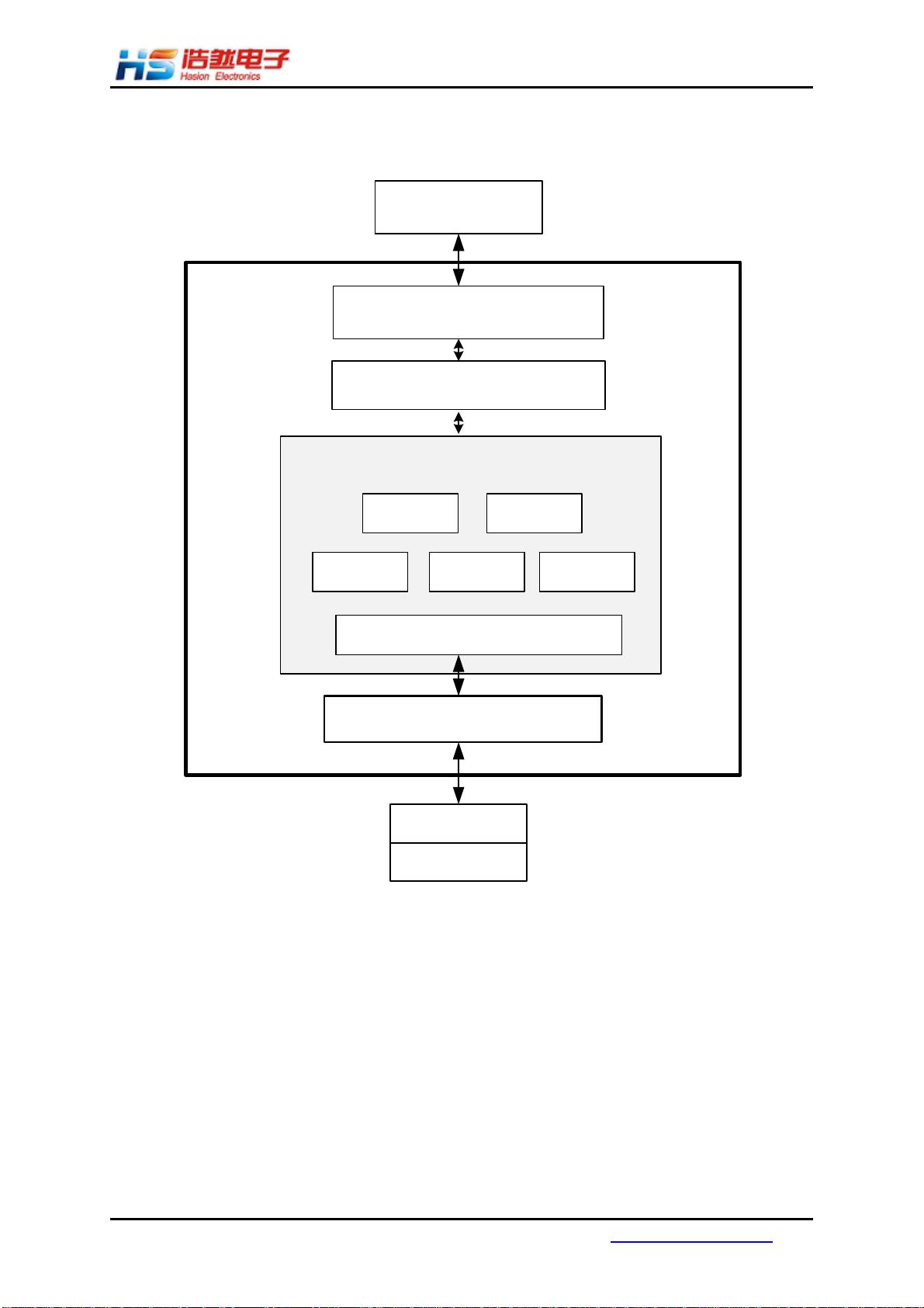
Block Diagram

© Copyright 2012 WIZnet Co., Inc. All rights reserved.
5
iEthernet W5200
Table of Contents
1 Pin Assignment............................................................................................ 8
1.1 MCU Interface Signals ....................................................................... 8
1.2 PHY Signals .................................................................................. 10
1.3 Miscellaneous Signals ...................................................................... 11
1.4 Power Supply Signals ...................................................................... 11
1.5 Clock Signals ................................................................................ 12
1.6 LED Signals .................................................................................. 13
2 Memory Map ............................................................................................ 14
3 W5200 Registers ........................................................................................ 15
3.1 common registers .......................................................................... 15
3.2 Socket registers ............................................................................ 16
4 Register Descriptions .................................................................................. 17
4.1 Common Registers ......................................................................... 17
4.2 Socket Registers ............................................................................ 24
5 Functional Descriptions ............................................................................... 42
5.1 Initialization ................................................................................ 42
5.2 Data Communications ..................................................................... 45
5.2.1 TCP ..................................................................................... 45
5.2.1.1 TCP SERVER ...................................................................... 46
5.2.1.2 TCP CLIENT ...................................................................... 53
5.2.2 UDP ..................................................................................... 54
5.2.2.1 Unicast and Broadcast ......................................................... 54
5.2.2.2 Multicast ......................................................................... 61
5.2.3 IPRAW ................................................................................... 64
5.2.4 MACRAW ................................................................................ 66
6 External Interface ..................................................................................... 72
6.1 SPI (Serial Peripheral Interface) mode ................................................. 72
6.2 Device Operations .......................................................................... 72
6.3 Process of using general SPI Master device ............................................ 73
7 Electrical Specifications .............................................................................. 78
7.1 Absolute Maximum Ratings ............................................................... 78
7.2 DC Characteristics ......................................................................... 78
7.3 POWER DISSIPATION(Vcc 3.3V Temperature 25°C) ................................... 78
7.4 AC Characteristics ......................................................................... 79
7.4.1 Reset Timing .......................................................................... 79
7.4.2 Crystal Characteristics .............................................................. 79
7.4.3 SPI Timing.............................................................................. 80


