W9825G6KH-带书签.pdf
需积分: 50 46 浏览量
2020-07-14
10:28:39
上传
评论
收藏 846KB PDF 举报


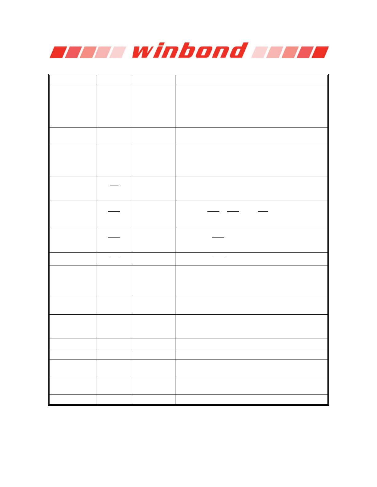
W9825G6KH
4 M 4 BANKS 16 BITS SDRAM
Publication Release Date: Mar. 20, 2017
Revision: A04
- 1 -
Table of Contents-
1. GENERAL DESCRIPTION ......................................................................................................... 3
2. FEATURES ................................................................................................................................. 3
3. ORDER INFORMATION ............................................................................................................. 4
4. PIN CONFIGURATION ............................................................................................................... 4
5. PIN DESCRIPTION ..................................................................................................................... 5
6. BLOCK DIAGRAM ...................................................................................................................... 6
7. FUNCTIONAL DESCRIPTION .................................................................................................... 7
7.1 Power Up and Initialization ............................................................................................. 7
7.2 Programming Mode Register .......................................................................................... 7
7.3 Bank Activate Command ................................................................................................ 7
7.4 Read and Write Access Modes ...................................................................................... 7
7.5 Burst Read Command .................................................................................................... 8
7.6 Burst Write Command .................................................................................................... 8
7.7 Read Interrupted by a Read ........................................................................................... 8
7.8 Read Interrupted by a Write ............................................................................................ 8
7.9 Write Interrupted by a Write ............................................................................................ 8
7.10 Write Interrupted by a Read ............................................................................................ 8
7.11 Burst Stop Command ..................................................................................................... 8
7.12 Addressing Sequence of Sequential Mode .................................................................... 9
7.13 Addressing Sequence of Interleave Mode ...................................................................... 9
7.14 Auto-precharge Command ........................................................................................... 10
7.15 Precharge Command .................................................................................................... 10
7.16 Self Refresh Command ................................................................................................ 10
7.17 Power Down Mode........................................................................................................ 11
7.18 No Operation Command ............................................................................................... 11
7.19 Deselect Command ...................................................................................................... 11
7.20 Clock Suspend Mode .................................................................................................... 11
8. OPERATION MODE ................................................................................................................. 12
9. ELECTRICAL CHARACTERISTICS ......................................................................................... 13
9.1 Absolute Maximum Ratings .......................................................................................... 13
9.2 Recommended DC Operating Conditions .................................................................... 13
9.3 Capacitance .................................................................................................................. 14
9.4 DC Characteristics ........................................................................................................ 14
9.5 AC Characteristics and Operating Condition ................................................................ 15
10. TIMING WAVEFORMS ............................................................................................................. 17
10.1 Command Input Timing ................................................................................................ 17
10.2 Read Timing .................................................................................................................. 18
10.3 Control Timing of Input/Output Data ............................................................................. 19
10.4 Mode Register Set Cycle .............................................................................................. 20
11. OPERATING TIMING EXAMPLE ............................................................................................. 21


剩余42页未读,继续阅读
资源评论


