


Service & Support
Answers for industry.
Cover
Positioning via pulse interface
Micro Automation Positioning - SERVO
FAQ July 2010

Question
2
Positioning via pulse interface
V1.8, Item-ID: 26513850
This entry is from the Service&Support portal of Siemens AG, Sector Industry,
Industry Automation and Drive Technologies. The general terms of use
(http://www.siemens.com/terms_of_use
) apply.
Clicking the link below directly displays the download page of this document.
http://support.automation.siemens.com/WW/view/en/
26513850
For questions about this document please use the following e-mail address:
mailto:online-support.i-ia@siemens.com

Table of content
Positioning via pulse interface
V1.8, Item-ID: 26513850 3
Table of content
1 Objective............................................................................................................. 5
2 Implementation .................................................................................................. 6
3 Positioning block library................................................................................... 8
3.1 Overview .............................................................................................. 8
3.2 General information.............................................................................. 9
3.2.1 Setup .................................................................................................... 9
3.2.2 Permanent assignment of I/Os........................................................... 10
3.2.3 Integrating the block library ................................................................ 10
3.3 Positioning blocks............................................................................... 12
3.3.1 Q0_x_CTRL ....................................................................................... 12
3.3.2 Scale_EU_Pulse / Scale_ Pulse_EU ................................................. 13
3.3.3 Q0_x_Home ....................................................................................... 14
3.3.4 Q0_x_MoveRelative ........................................................................... 16
3.3.5 Q0_x_MoveAbsolute.......................................................................... 17
3.3.6 Q0_x_MoveVelocity ........................................................................... 19
3.3.7 Q0_x_Stop ......................................................................................... 20
3.3.8 Q0_x_LoadPos................................................................................... 20
3.4 Calibration .......................................................................................... 21
3.4.1 Tuning factor ...................................................................................... 21
3.4.2 Application area.................................................................................. 22
3.4.3 Determining the tuning factor ............................................................. 23
4 Software examples for positioning via pulse interface............................... 24
Preliminary remark ............................................................................. 24
Download ........................................................................................... 24
Hardware............................................................................................ 24
Operation............................................................................................ 25
4.1 Task.................................................................................................... 26
4.2 Description of the demo project “MAP SERV Q0.0.mwp”.................. 26
4.2.1 Overview of the demo program “MAIN” ............................................. 26
4.2.2 Calculating the minimum frequency “Velocity_SS” ............................ 27
4.2.3 Calculating the maximum frequency “Velocity_Max” ......................... 27
4.2.4 Calculating the target frequency “Velocity” ........................................ 28
4.2.5 Calculating the maximum acceleration and deceleration time
“accel_dec_time” ................................................................................ 29
4.2.6 Parameterizing the control block “Q0_0_CTRL” ................................ 29
4.2.7 Changing the default values (optional)............................................... 30
4.2.8 Reference point search ...................................................................... 31
4.2.9 Converting the position data of point A (120 mm) into the
corresponding pulse position ............................................................. 32
4.2.10 Moving to point A................................................................................ 33
4.2.11 Moving to point B................................................................................ 33
4.2.12 Resetting the position counter............................................................ 35
4.2.13 Realizing the jog mode....................................................................... 35
4.2.14 Determining the traveled distance...................................................... 36

Table of content
4
Positioning via pulse interface
V1.8, Item-ID: 26513850
5 Positioning diagrams for the function “Q0_x_Home”................................. 37
Overview 37
5.1 Start_Dir=0, Final_Dir=0..................................................................... 38
5.1.1 Start position: to the right of the reference point ................................ 38
5.1.2 Start position: to the left of the reference point .................................. 38
5.2 Start_Dir=0, Final_Dir=1..................................................................... 39
5.2.1 Start position: to the right of the reference point ................................ 39
5.2.2 Start position: to the left of the reference point .................................. 39
5.3 Start_Dir=1, Final_Dir=0..................................................................... 40
5.3.1 Start position: to the left of the reference point .................................. 40
5.3.2 Start position: to the right of the reference point ................................ 40
5.4 Start_Dir=1, Final_Dir=1..................................................................... 41
5.4.1 Start position: to the left of the reference point .................................. 41
5.4.2 Start position: to the right of the reference point ................................ 41
Objective
Positioning via pulse interface Entry-ID: 26513850
Positioning via pulse interface
V1.8, Item-ID: 26513850 5
Copyright Siemens AG 2010 All rights reserved
MAP_SERV_e_new.doc
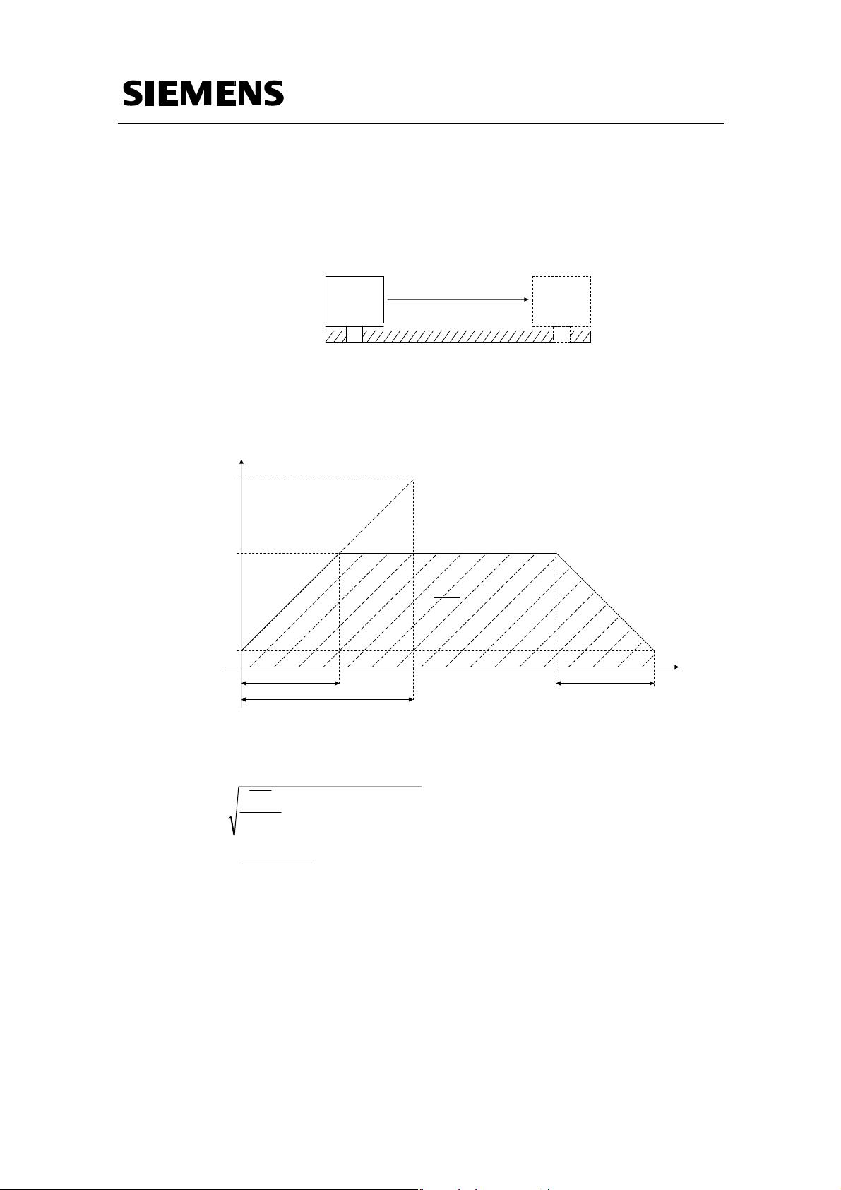
1 Objective
The aim is to move an object from point A to point B, e.g. by using a motor spindle.
Figure 1-1
AB
To this end, the object is accelerated to a specified speed v within the time interval
∆T. The spindle moves with the speed v, and in order to reach the end position B, it
is decelerated to zero within a second identical time interval. We obtain the
distance from A to B from the area of the v-t diagram:
Figure 1-2
v
t
AB
A
B
∆T
max
∆T
A
c
c
e
l
e
r
a
t
i
o
n
D
e
c
e
le
r
a
t
io
n
v
max
v
min
∆T
By specifying v
min
, v
max
, ∆T
max
and the distance from A to B, we obtain the condition
for the maximum achievable velocity v and the acceleration and deceleration time
∆T:
max
minmax
min
2
minminmax
max
)(
T
vv
vv
T
vvv
T
AB
v
Δ⋅
−
−
=Δ
+−⋅
Δ
≤


