没有合适的资源?快使用搜索试试~ 我知道了~
资源推荐
资源详情
资源评论
POWER DRIVER FOR STEPPER MOTORS INTEGRATED CIRCUITS
TRINAMIC Motion Control GmbH & Co. KG
Hamburg, Germany
TMC5130A-TA DATASHEET
FEATURES AND BENEFITS
2-phase stepper motors up to 2A coil current (2.5A peak)
Motion Controller with sixPoint™
ramp
Step/Dir Interface with microstep interpolation microPlyer™
Voltage Range 4.75… 46V DC
SPI & Single Wire UART
Encoder Interface and 2x Ref.-Switch Input
Highest Resolution 256 microsteps per full step
stealthChop™ for extremely quiet operation and smooth motion
spreadCycle™ highly dynamic motor control chopper
dcStep™ load dependent speed control
stallGuard2™ high precision sensorless motor load detection
coolStep™ current control for energy savings up to 75%
Integrated Current Sense Option
Passive Braking and freewheeling mode
Full Protection & Diagnostics
Compact Size 9x9mm
2
TQFP48 package
APPLICATIONS
Textile, Sewing Machines
Factory Automation
Lab Automation
Liquid Handling
Medical
Office Automation
CCTV, Security
ATM, Cash recycler
POS
Pumps and Valves
Heliostat Controller
DESCRIPTION
The TMC5130A is a high performance
stepper motor controller and driver IC
with serial communication interfaces. It
combines a flexible ramp generator for
automatic target positioning with
industries’ most advanced stepper motor
driver. Based on TRINAMICs sophisticated
stealthChop chopper, the driver ensures
absolutely noiseless operation combined
with maximum efficiency and best motor
torque. High integration, high energy
efficiency and a small form factor enable
miniaturized and scalable systems for
cost effective solutions. The complete
solution reduces learning curve to a
minimum while giving best performance
in class.
Universal high voltage controller/driver for two-phase bipolar stepper motor. stealthChop™ for quiet
movement. Integrated MOSFETs for up to 2 A motor current per coil. With Step/Dir Interface and SPI.
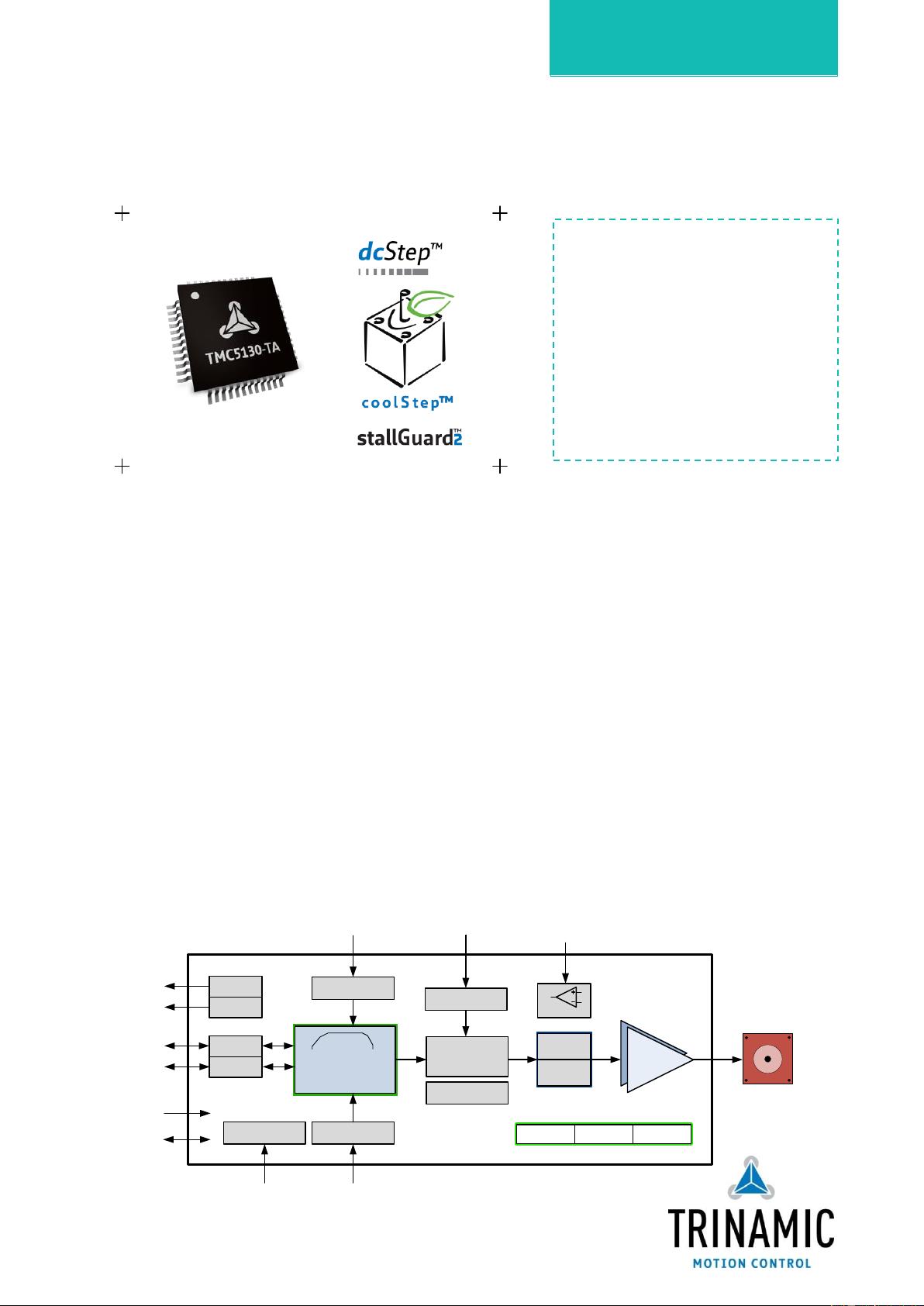
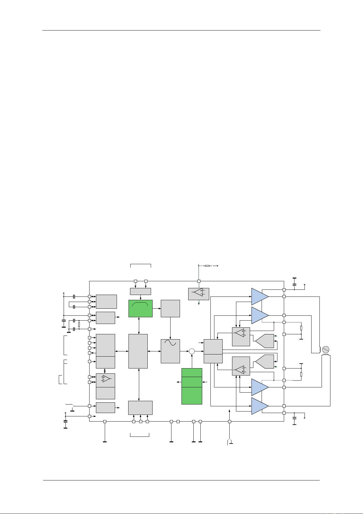
BLOCK DIAGRAM
spreadCycle
stealthChop
MOTION CONTROLLER
with Linear 6 Point
RAMP Generator
DRIVER
TMC5130A
Programmable
256 µStep
Sequencer
Protection
& Diagnostics
Ref. Switches
SPI
stallGuard2 coolStep dcStep
Power
Supply
Charge
Pump
ABN
Motor
Encoder Unit
Step/Dir
Step Multiplyer
spreadCycle
stealthChop
DAC Reference
IREF
optional current scaling
Reference Switch
Processing
Interrupts
Position
Pulse Output
UART
Single Wire
SPI to
Master
UART
CLK
CLK
Oscillator / Selector
TMC5130A DATASHEET (Rev. 1.13 / 2016-SEP-21) 2
www.trinamic.com
APPLICATION EXAMPLES: HIGH VOLTAGE – MULTIPURPOSE USE
The TMC5130A scores with complete motion controlling features, integrated power stages, and power
density. It offers a versatility that covers a wide spectrum of applications from battery powered systems up
to embedded applications with 2A motor current per coil. The TMC5130A contains the complete intelligence
which is required to drive a motor. Receiving target positions the TMC5130A manages motor movement.
Based on TRINAMICs unique features stallGuard2, coolStep, dcStep, spreadCycle, and stealthChop, the
TMC5130A optimizes drive performance. It trades off velocity vs. motor torque, optimizes energy efficiency,
smoothness of the drive, and noiselessness. The small form factor of the TMC5130A keeps costs down and
allows for miniaturized layouts. Extensive support at the chip, board, and software levels enables rapid
design cycles and fast time-to-market with competitive products. High energy efficiency and reliability
deliver cost savings in related systems such as power supplies and cooling.
CPU
TMC5130A
High-Level
Interface
SPI
CPU
High-Level
Interface
TMC5130A
TMC5130A
Up to 255 TMC5130
can be addressed.
UART
MINIATURIZED DESIGN FOR ONE STEPPER MOTOR
COMPACT DESIGN FOR UP TO 255 STEPPER MOTORS
M
Encoder
Ref.
Switches
M
M
Addr.
Addr.
TMC5130-EVAL EVALUATION BOARD
ORDER CODES
Order code
Description
Size [mm
2
]
TMC5130A-TA
1-axis dcStep, coolStep, and stealthChop controller/driver;
TQFP48
9 x 9
TMC5130-EVAL
Evaluation board for TMC5130A two phase stepper motor
controller/driver
85 x 55
STARTRAMPE
Baseboard for TMC5130-EVAL and further evaluation boards.
85 x 55
ESELSBRÜCKE
Connector board for plug-in evaluation board system.
61 x 38
An ABN encoder interface with scaler
unit and two reference switch inputs are
used to control motor movement.
An application with 2 stepper motors is
shown. Additionally, the ABN Encoder
interface and two reference switches can
be used for each motor. A single CPU
controls the whole system. The CPU-
board and the controller / driver boards
are highly economical and space saving.
The TMC5130-EVAL is part of
TRINAMICs universal evaluation board
system which provides a convenient
handling of the hardware as well as a
user-friendly software tool for
evaluation. The TMC5130 evaluation
board system consists of three parts:
STARTRAMPE (base board),
ESELSBRÜCKE (connector board
including several test points), and
TMC5130-EVAL.
TMC5130A DATASHEET (Rev. 1.13 / 2016-SEP-21) 3
www.trinamic.com
Table of Contents
1 PRINCIPLES OF OPERATION ......................... 5
1.1 KEY CONCEPTS ................................................ 7
1.2 CONTROL INTERFACES ..................................... 7
1.3 SOFTWARE ...................................................... 7
1.4 MOVING AND CONTROLLING THE MOTOR ........ 8
1.5 STEALTHCHOP DRIVER ..................................... 8
1.6 STALLGUARD2 – MECHANICAL LOAD SENSING8
1.7 COOLSTEP – LOAD ADAPTIVE CURRENT
CONTROL ...................................................................... 9
1.8 DCSTEP – LOAD DEPENDENT SPEED CONTROL 9
1.9 ENCODER INTERFACE ....................................... 9
2 PIN ASSIGNMENTS ......................................... 10
2.1 PACKAGE OUTLINE ........................................ 10
2.2 SIGNAL DESCRIPTIONS ................................. 10
3 SAMPLE CIRCUITS .......................................... 13
3.1 STANDARD APPLICATION CIRCUIT ................ 13
3.2 REDUCED NUMBER OF COMPONENTS ............. 14
3.3 INTERNAL RDSON SENSING .......................... 14
3.4 EXTERNAL 5V POWER SUPPLY ...................... 15
3.5 PRE-REGULATOR FOR REDUCED POWER
DISSIPATION .............................................................. 16
3.6 5V ONLY SUPPLY .......................................... 17
3.7 HIGH MOTOR CURRENT ................................. 18
3.8 DRIVER PROTECTION AND EME CIRCUITRY ... 20
4 SPI INTERFACE ................................................ 21
4.1 SPI DATAGRAM STRUCTURE ......................... 21
4.2 SPI SIGNALS ................................................ 22
4.3 TIMING ......................................................... 23
5 UART SINGLE WIRE INTERFACE ................ 24
5.1 DATAGRAM STRUCTURE ................................. 24
5.2 CRC CALCULATION ....................................... 26
5.3 UART SIGNALS ............................................ 26
5.4 ADDRESSING MULTIPLE SLAVES .................... 27
6 REGISTER MAPPING ....................................... 29
6.1 GENERAL CONFIGURATION REGISTERS .......... 30
6.2 VELOCITY DEPENDENT DRIVER FEATURE
CONTROL REGISTER SET ............................................. 33
6.3 RAMP GENERATOR REGISTERS ....................... 35
6.4 ENCODER REGISTERS ..................................... 40
6.5 MOTOR DRIVER REGISTERS ........................... 42
7 STEALTHCHOP™ .............................................. 51
7.1 TWO MODES FOR CURRENT REGULATION ...... 51
7.2 AUTOMATIC SCALING .................................... 52
7.3 VELOCITY BASED SCALING ............................ 54
7.4 COMBINING STEALTHCHOP AND SPREADCYCLE
56
7.5 FLAGS IN STEALTHCHOP ................................ 57
7.6 FREEWHEELING AND PASSIVE BRAKING ........ 58
8 SPREADCYCLE AND CLASSIC CHOPPER ... 59
8.1 SPREADCYCLE CHOPPER ................................ 60
8.2 CLASSIC CONSTANT OFF TIME CHOPPER ...... 63
8.3 RANDOM OFF TIME ...................................... 64
8.4 CHOPSYNC2 FOR QUIET 2-PHASE MOTOR .... 65
9 ANALOG CURRENT CONTROL AIN ............. 66
10 SELECTING SENSE RESISTORS ............... 67
11 INTERNAL SENSE RESISTORS ................. 69
12 VELOCITY BASED MODE CONTROL ....... 71
13 DRIVER DIAGNOSTIC FLAGS .................. 73
13.1 TEMPERATURE MEASUREMENT ....................... 73
13.2 SHORT TO GND PROTECTION ....................... 73
13.3 OPEN LOAD DIAGNOSTICS ........................... 73
14 RAMP GENERATOR ..................................... 74
14.1 REAL WORLD UNIT CONVERSION ................. 74
14.2 MOTION PROFILES ........................................ 75
14.3 VELOCITY THRESHOLDS ................................. 77
14.4 REFERENCE SWITCHES .................................. 78
14.5 EXTERNAL STEP/DIR DRIVER ...................... 79
15 STALLGUARD2 LOAD MEASUREMENT ... 80
15.1 TUNING STALLGUARD2 THRESHOLD SGT ..... 81
15.2 STALLGUARD2 UPDATE RATE AND FILTER .... 83
15.3 DETECTING A MOTOR STALL ......................... 83
15.4 HOMING WITH STALLGUARD ......................... 83
15.5 LIMITS OF STALLGUARD2 OPERATION .......... 83
16 COOLSTEP OPERATION ............................. 84
16.1 USER BENEFITS ............................................. 84
16.2 SETTING UP FOR COOLSTEP .......................... 84
16.3 TUNING COOLSTEP ........................................ 86
17 STEP/DIR INTERFACE ................................ 87
17.1 TIMING ......................................................... 87
17.2 CHANGING RESOLUTION ............................... 88
17.3 MICROPLYER STEP INTERPOLATOR AND STAND
STILL DETECTION ....................................................... 89
18 DIAG OUTPUTS ........................................... 90
18.1 STEP/DIR MODE ......................................... 90
18.2 MOTION CONTROLLER MODE ........................ 90
19 DCSTEP .......................................................... 92
19.1 USER BENEFITS ............................................. 92
19.2 DESIGNING-IN DCSTEP ................................. 92
19.3 DCSTEP INTEGRATION WITH THE MOTION
CONTROLLER .............................................................. 93
19.4 STALL DETECTION IN DCSTEP MODE ............ 93
19.5 MEASURING ACTUAL MOTOR VELOCITY IN
DCSTEP OPERATION ................................................... 94
19.6 DCSTEP WITH STEP/DIR INTERFACE ........... 95
目录
工作原理
关键概念
控制接口
软件
移动和控制电机
节能驱动
失速检测-机械负载检测
静步-自适应负载电流控制
自适应负载的速度控制
编码器接口
针脚位分配
外部封装
信号描述
5V供电
简化结构
内部RDSon传感器
外部5V供电
PRE调节器应用到节能
大电流电机
驱动保护和EME电路
SPI通用接口
SPI数据包结构
SPI信号
SPI时钟
串口信号接口
数据包结构
CRC校验
串口信号
多从机寻址
寄存器映射
通用寄存器配置
驱动速度相关的
参数控制和设定
斜坡发生器寄存器
编码器寄存器
电机驱动寄存器
隐形斩波
两种电流调节模式
电流自动缩放
基于速度的自动缩放
优速控制
隐形斩波和周期扩展相结合
在隐形斩波中的标志
惯性转动和被动刹车
周期扩展和经典斩波
周期扩展斩波
经典常数斩波
随机断开时间
适用于静音两相
电机
模拟电流输入控
制
选择电阻值
内部电阻值
基于速度的模
式控制
驱动诊断标志
温度测量
短路保护
断路诊断
斜坡发生器
时钟转换
运动简介,参考6.3
速度阈值
极限位置
外部步进和
方向驱动
负载失速检测
失速检测阈值
调节
失速检测
速度更新
和过滤
检测一个电机失速
归零过程带失速检测
失速检测的使用
限制
静步操作
使用优点
设置静步
调优静步
步进和方向接口
时序
改变分辨率
单片机的步进插补和静态检测
内部报警输出
步进和方向模式
运动控制模式
使用优点
优步的设计
优步和动作控制器的结合
失速检测在优
步模式
在优步操作中测量电机真实运行速度
优步和步进方向模式的接
口
采样电路
TMC5130A DATASHEET (Rev. 1.13 / 2016-SEP-21) 4
www.trinamic.com
20 SINE-WAVE LOOK-UP TABLE ................... 98
20.1 USER BENEFITS ............................................. 98
20.2 MICROSTEP TABLE ........................................ 98
21 EMERGENCY STOP ....................................... 99
22 ABN INCREMENTAL ENCODER
INTERFACE .............................................................. 100
22.1 ENCODER TIMING ....................................... 101
22.2 SETTING THE ENCODER TO MATCH MOTOR
RESOLUTION ............................................................ 101
22.3 CLOSING THE LOOP .................................... 102
23 DC MOTOR OR SOLENOID .................... 103
23.1 SOLENOID OPERATION ............................... 103
24 QUICK CONFIGURATION GUIDE ......... 104
25 GETTING STARTED .................................. 109
25.1 INITIALIZATION EXAMPLES ......................... 109
26 STANDALONE OPERATION .................... 110
27 EXTERNAL RESET ...................................... 113
28 CLOCK OSCILLATOR AND INPUT ........ 113
28.1 USING THE INTERNAL CLOCK...................... 113
28.2 USING AN EXTERNAL CLOCK ....................... 114
28.3 CONSIDERATIONS ON THE FREQUENCY ........ 114
29 ABSOLUTE MAXIMUM RATINGS .......... 115
30 ELECTRICAL CHARACTERISTICS .......... 115
30.1 OPERATIONAL RANGE ................................. 115
30.2 DC AND TIMING CHARACTERISTICS ............ 116
30.3 THERMAL CHARACTERISTICS........................ 119
31 LAYOUT CONSIDERATIONS................... 120
31.1 EXPOSED DIE PAD ...................................... 120
31.2 WIRING GND ............................................ 120
31.3 SUPPLY FILTERING ...................................... 120
31.4 LAYOUT EXAMPLE ....................................... 121
32 PACKAGE MECHANICAL DATA .............. 123
32.1 DIMENSIONAL DRAWINGS TQFP48-EP ..... 123
32.2 PACKAGE CODES ......................................... 124
33 DESIGN PHILOSOPHY ............................. 125
34 DISCLAIMER ............................................... 125
35 ESD SENSITIVE DEVICE.......................... 125
36 TABLE OF FIGURES .................................. 126
37 REVISION HISTORY ................................. 128
38 REFERENCES ............................................... 128
正弦波查找表
使用优点
紧急停止
ABN增量编码器接口
编码器的时序
设置编码器匹配电机分辨率
闭合回路
直流电机和螺纹管
快速配置指南
入门指南;准备开始
初始化的例子
独立操作
外部复位
时钟振荡器与输入
使用内部时钟
使用外部时钟
对频率的考虑
绝对最大额定参数
电特性
操作范围
直流和定时特性
热特性
布线考量
包装机械的数据
设计原理
免责声明
静电敏感设备
数据表
修订历史
参考文献
TMC5130A DATASHEET (Rev. 1.13 / 2016-SEP-21) 5
www.trinamic.com
1 Principles of Operation
The TMC5130A motion controller and driver chip is an intelligent power component interfacing
between CPU and stepper motor. All stepper motor logic is completely within the TMC5130A. No
software is required to control the motor – just provide target positions. The TMC5130A offers a
number of unique enhancements which are enabled by the system-on-chip integration of driver and
controller. The sixPoint ramp generator of the TMC5130A uses stealthChop, dcStep, coolStep, and
stallGuard2 automatically to optimize every motor movement.
THE TMC5130A OFFERS THREE BASIC MODES OF OPERATION:
MODE 1: Full Featured Motion Controller & Driver
All stepper motor logic is completely within the TMC5130A. No software is required to control the
motor – just provide target positions. Enable this mode by tying low pin SD_MODE.
MODE 2: Step & Direction Driver
An external high-performance S-ramp motion controller like the TMC4361 or a central CPU generates
step & direction signals synchronized to other components like additional motors within the system.
The TMC5130A takes care of intelligent current and mode control and delivers feedback on the state of
the motor. The microPlyer automatically smoothens motion. Leave open SD_MODE and SPI_MODE.
MODE 3: Simple Step & Direction Driver
The TMC5130A positions the motor based on step & direction signals. The microPlyer automatically
smoothens motion. No CPU interaction is required; configuration is done by hardware pins. Basic
standby current control can be done by the TMC5130A. Optional feedback signals allow error detection
and synchronization. Enable this mode by tying low pin SPI_MODE.
Diff. Tranceiver
Half Bridge 1
Half Bridge 2
+V
M
VS
current
comparator
2 phase
stepper
motor
N
S
Stepper driver
Protection
& diagnostics
programmable
sine table
4*256 entry
DAC
stallGuard2™
coolStep™
x
OA1
OA2
BRA
spreadCycle &
stealthChop
Chopper
VCC_IO
TMC 5130A
Stepper motor driver /
controller
SPI interface
CSN
SCK
SDO/NAO
SDI/NAI
linear 6 point RAMP
generator
reference switch
processing
Step &
Direction pulse
generation
REFL
Motion control
REFR
Half Bridge 1
Half Bridge 2
VS
current
comparator
DAC
OB1
OB2
BRB
Control register
set
Single wire
interface
(-TA pckg only)
CLK oscillator/
selector
5V Voltage
regulator
charge pump
CPO
CPI
VCP
22n
100n
SWN_DIAG0
SW_SEL
CLK_IN
Interface
SWP_DIAG1
+V
M
5VOUT
VSA
4.7µ
+V
IO
Encoder
unit
A B N
INT & position
pulse output
DRV_ENN
DRV_ENN
GNDP
GNDP
GNDA
F
F
F = 60ns spike filter
TST_MODE
dcStep™
DIE PAD
SPI™
single wire
UART
opt. ext. clock
10-16MHz
3.3V or 5V
I/O voltage
100n
100n
100n
100n
interface selection
(-TA package only)
Opt. interrupt out
reference / stop switches
opt. driver enable
R
S
R
S
ENCB
ENCA
ENCN
ISENSE
ISENSE
ISENSE
ISENSE
+V
M
DAC Reference
AIN_IREF
IREF
IREF
IREF
SD_MODE
SPI_MODE
PU
PU
PU
PU
PD
PDD
PMD
PU=166K pullup resistor to VCC
PD=166k pull down resistor to GND
PDD=100k pulldown
PMD=50k to VCC/2
PU
PU
PU
PU
PU=166K pullup to VCC
PU
Opt. poscomp out
leave open
optional current scaling
Optional for internal
current sensing.
R
REF
=9K1 allows for
maximum coil current.
R
S
=0R15 allows for
maximum coil current;
Use low inductance
SMD resistor type.
Tie BRA and BRB to
GND for internal
current sensing
R
REF
5VOUT
2R2
470n
2R2 and 470n are optional
filtering components for
best chopper precision
VCC
Optional incremental
encoder inputs
coolStep
&
stealthChop
motor driver
Figure 1.1 TMC5130A basic application block diagram with motion controller
TMC5130A运动控制器和驱动芯片是CPU和步进电机之间的智能功率器件接口。所有步进电机逻辑完全在TMC51 30A内。没
有软件需要控制电机-只要提供目标位置。TMC5130A提供了许多独特的增强功能,这些功能通过驱动器和控制器的片上
系统集成来实现。TMC51 30A的六点斜坡发生器使用StualthCHOP、DCSTEP、CooStand,以及STALARGADD2自动优化每台
电机的运动
TMC51 30A提供三种基本操作模式:
模式1:全功能运动控制器和驱动程序
所有的步进电机逻辑完全在TMC5130A内。不需要任何软件来控制
电机-只要提供目标位置。通过连接低引脚SD_MODE启用此模式。
模式2:步进和方向驱动
外部高性能的S-斜坡运动控制器,如TMC4361或中央CPU,产生与其他同步的步
进和方向信号。组件,如系统内的附加电机。TMC5130A负责智能电流和模式控
制,并在电机运动时提供状态反馈。微动器自动平滑运动。打开SDK模式和
SPIX模式。
模式3:简单的步骤和方向驱动程序
TMC51 30A基于步进方向信号定位电机。微动器自动平滑运动。不需要CPU交互;配置是通过硬件引脚完成的。
基本待机电流控制可以由TMC51 30A完成。可选的反馈信号允许错误检测和同步。通过连接低SPI_MODE引脚来实现这个
模式。
参考/停止开关
参考开关处理
线性6点斜坡
发生器
可选电流缩放
可选内部电流缩放器,RREF=9K1
时允许最大线圈电流
DAC参考
充电泵
5伏电压监控
微分传输电路
位置脉冲输出
时钟振荡器
编码器单元
可选的增量
编码器的输入
图1.1带有运动控制器的TMC5130A基本应用框图
控制寄存器组
步进/方向
脉冲发生器
可编程的
正弦表
2相步进
电动机
剩余127页未读,继续阅读
资源评论
鸳鸯冰笔
- 粉丝: 91
- 资源: 6
上传资源 快速赚钱
- 我的内容管理 展开
- 我的资源 快来上传第一个资源
- 我的收益 登录查看自己的收益
- 我的积分 登录查看自己的积分
- 我的C币 登录后查看C币余额
- 我的收藏
- 我的下载
- 下载帮助
最新资源
- rain-ripples.PNG
- Gitlab: Python项目CI/CD实践 > fastapi-t1 > Dockerfile
- springboot的校园失物招领系统源码.zip
- Skeleton-Low Poly 低多边形骨架模型Unity插件美术资源包unitypackage
- Direct X修复工具
- Android教你如何一分钟实现下拉刷新功能项目完整实例代码
- 基于SpringBoot校园失物招领系统 前后端分离项目(mysql脚本在后端程序中).zip
- 使用JSTL需要的jar包程序文件
- 潘晓庆 321023199101293449。23-24年.xls
- 目标检测数据集(YOLOV5目录格式):花生检测(2类别,包含训练集、验证集)
资源上传下载、课程学习等过程中有任何疑问或建议,欢迎提出宝贵意见哦~我们会及时处理!
点击此处反馈
安全验证
文档复制为VIP权益,开通VIP直接复制
信息提交成功