DC-DC转换器的恒流源控制.pdf
需积分: 49 190 浏览量
2019-09-17
04:15:49
上传
评论 1
收藏 1.2MB PDF 举报

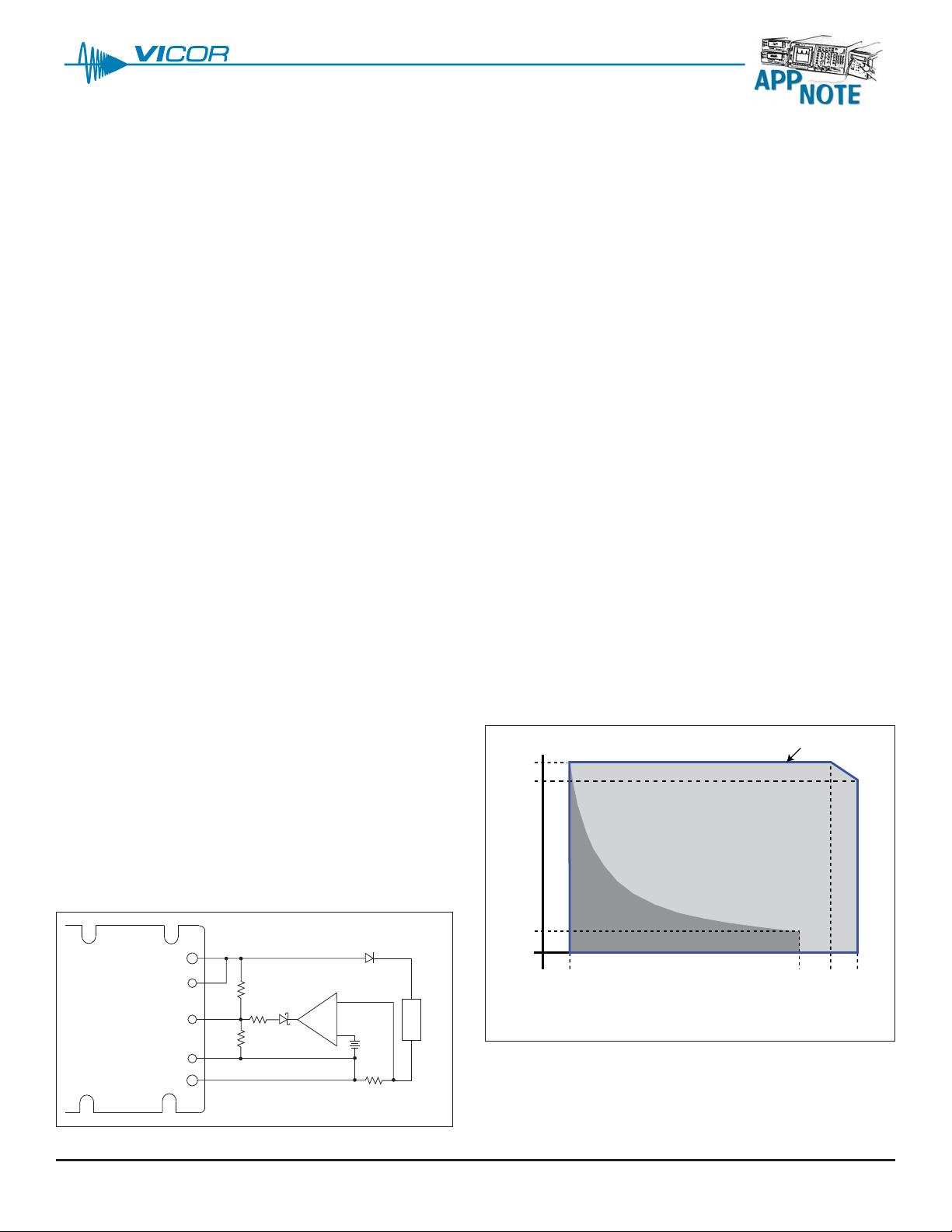
I
max
0.911
max
0.111
max
0 A
0 V 0.1 V
nom 0.9 Vnom Vnom 1.1 Vnom
Preload may
be required
Safe Operating Boundary
V
nom
is the nominal output voltage of the converter
I
max
is the rated output power of the converter divided by V
nom
page 1 of 9
Introduction ................................................................1
Theory of Operation...................................................1
Power Limitations .......................................................1
Voltage Loop Stability ................................................2
Current Loop Compensation......................................3
Current Control Example............................................5
Battery Charger Circuit Description ......................5
Component Values .................................................6
VI-200 / VI-J00 Converters ......................................9
Introduction
Vicor’s VI-200/VI-J00 and Maxi, Mini and Micro family
DC-DC converters are voltage regulating devices, but their
wide trim range makes it possible to use them as efficient
high-power current sources. Current regulation can be
implemented through the addition of an external control
loop and current-sense resistor. Such a design must
take into account the power limitations of the DC-DC
converter and must ensure the stability of the converter’s
voltage loop. In addition to these considerations, this
application note covers compensation of the external
current-control loop and a design example for a simple
battery charger.
Theory of Operation
Figure 1 shows a current control configuration for
applications requiring basic constant current control.
The error amplifier compares the reference voltage to the
voltage across the shunt resistor and pulls down the
converter SC pin until they are equal. The error amplifier
is compensated to stabilize this feedback loop.
The pull up / down network (R
u
, R
d
and R
s
) allows the
error amplifier to vary the output of the converter by trim-
ming the SC/ TRIM pin while keeping the pin from being
driven too high or too low.
The diode in series with the positive lead isolates the
output of the converter in the event of a failure. It is
required when the load can store significant energy,
e.g., with a battery or capacitor.
Circuit V
cc
can be provided externally or generated
directly from the module output using a regulator.
The latter option may require that the minimum voltage
at the output for the converter be increased.
Power Limitations
Maxi, Mini and Micro modules can be trimmed from
10% to 110% of their nominal output voltages.
The trim range for the VI-200 / VI-J00 family is 50% to
110% for most modules. These trim restrictions bound
the load impedances for which the module can maintain
constant current.
Figure 2 shows the Safe Operation Area (SOA) of a Maxi,
Mini or Micro converter. A properly designed current
source will operate on a horizontal line inside this area.
Figure 1 — Current control block diagram
Figure 2 — Maxi, Mini and Micro safe operating area
Constant Current Control for
DC-DC Converters
–OUT
–S
+S
+OUT
Load
R
shunt
R
u
–
+
SC (Maxi, Mini, Micro)
TRIM (VI-200 / VI-J00)
R
d
R
s
V
ref
+
资源评论


