4 of 42
Version 07.04.2011
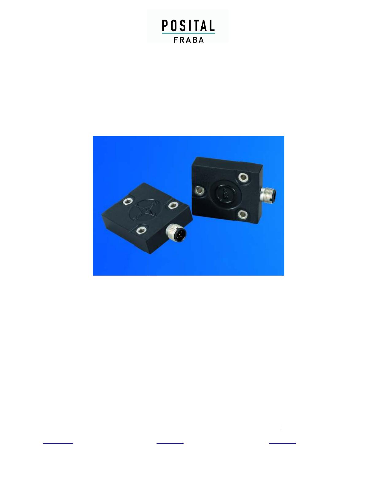
ACCELENS (ACS) ANALOG
1. Introduction
This manual explains how to install and configure
the ACS gravity referenced inclinometers
(suitable for industrial, military and heavy duty
applications) with an Analog + RS232 interface.
1.1 ACCELENS (ACS)
ACCELENS inclinometers sense and measure
the angle of tilt (Inclination/Slope/Elevation) of an
object with respect to the force of gravity. The
angle is measured with the relative change in
electrical capacitance.
The basic principle behind this ACS inclinometer
is a Micro-Electro-Mechanical System (MEMS)
sensor cell that is embedded to a fully molded
ASIC. A simplified version of the sensor consists
of two electrodes, one is fixed, and the other is
flexible (connected with spring elements). When
the inclinometer is parallel to the surface of
measurement, a corresponding capacitance is
measured. If the sensor is tilted, the flexible
electrode will change its position relative to the
fixed electrode. This results in a change of the
capacitance between the two electrodes which is
measured by the sensor cell. The change of the
capacitance is converted to a corresponding
inclination value.
The MEMS sensor cell in ACS consists of a
micromechanical structure with an array of
electrodes for better accuracy. Under the
influence of gravity, the distance between some
electrodes change and this distance can be
detected by measuring the capacitance between
the electrodes, as explained above. This
technology is available in different grades and
lower grades have entered mass markets like
mobile phones or tablet computers.
The ACS series of inclinometers are available in
two variants. First, a single axis measurement
variant with a range of 0-360° and the other
variant, a dual axis measurement capable ACS
model with a range of ±80°.
Absolute inclinometers identify all the points of a
movement by means of an unambiguous signal.
Due to their capacity to give clear and exact
values to all inclinations positions, inclinometers
have become one of the interesting alternatives
to singleturn absolute (and incremental) encoders
and a link between the mechanical and control
systems.
Benefits of ACS:
•
Small Size and Cost Efficient
•
High Protection Class
•
High Accuracy
•
Very Robust
1.2 Analog Interface
The analog interface is one of the most common
and simplest of the interfaces. It is compatible
from simple multi-meters to complex control
systems and PLCs.
An analog signal is a continuous signal which is
analogous i.e. comparable to another time
varying signal. In our case the variation of current
or voltage signal from ACS is analogous to the
variation of measured position.
Any information may be conveyed by an analog
signal; often such a signal is a measured
response to changes in physical phenomena,
such as sound, light, temperature, position, or
pressure, and is achieved using a transducer.