没有合适的资源?快使用搜索试试~ 我知道了~
温馨提示
试读
16页
电缆屋顶结构仅在20世纪后期才在大跨度结构中广泛使用。 但是,它们仍然代表了一种相对较新的屋顶结构形式,尤其是在目前采用小跨度创新结构解决方案的情况下。 本文对结构工程界的贡献在于对建造简单的电缆屋面结构的兴趣增加。 自1996年9月竣工以来,这种小型电缆屋顶结构已被公认为是有趣的建筑和结构实例。 文字描述了小型电缆屋顶的设计和施工方面,该小型电缆屋顶被设计为巴西圣保罗的圣何塞·里约·帕尔多市露天剧院舞台的屋顶。 呈双曲线抛物面形状的电缆网络锚固在钢筋混凝土边缘环中。 环的轴在地面上的投影为椭圆形。 工程的各个阶段均受过专门训练的工人受雇,该工程于1996年9月完成。
资源推荐
资源详情
资源评论
Open Journal of Civil Engineering, 2017, 7, 453-467
http://www.scirp.org/journal/ojce
ISSN Online: 2164-3172
ISSN Print: 2164-3164
DOI:
10.4236/ojce.2017.73031 Sep. 1, 2017 453
Open Journal of Civil Engineering
Practical Aspects of the Design and
Construction of a Small Cable Roof Structure
Vinicius Fernando Arcaro, Luiz Carlos de Almeida
University of Campinas, Campinas, Brazil
Abstract
Cable roof structures have only become widespread in large span structures in
the latter part of the twentieth century. However, they still represent a rel
a-
tively new form of roof construction, especially
as in the present case of a
small span innovative structural solution.
The contribution of this text to the
structural engineering community lies in the increased interest in build
ing
simple cable roof structures. Si
nce its completion in September 1996, this
small cable roof structure has been recognized as an interesting architectural
and structural example. The text describes aspects of the design and constru
c-
tion of a small cable roof that was designed as a roof for an open-
air theater
stage for the city of Sao Jose do Rio Pardo, Sao Paulo, Brazil. A cable network,
in the shape of a hyperbolic paraboloid surface, is anchored in a
reinforced
concrete edge ring. The projection of the ring’s axis onto the ground plane is
an ellipse. Workers with specialized training were employed in the various
stages of the construction, which was completed in September 1996.
Keywords
Cable Roofs, Hypar Roofs, Tension Structures
1. Introduction
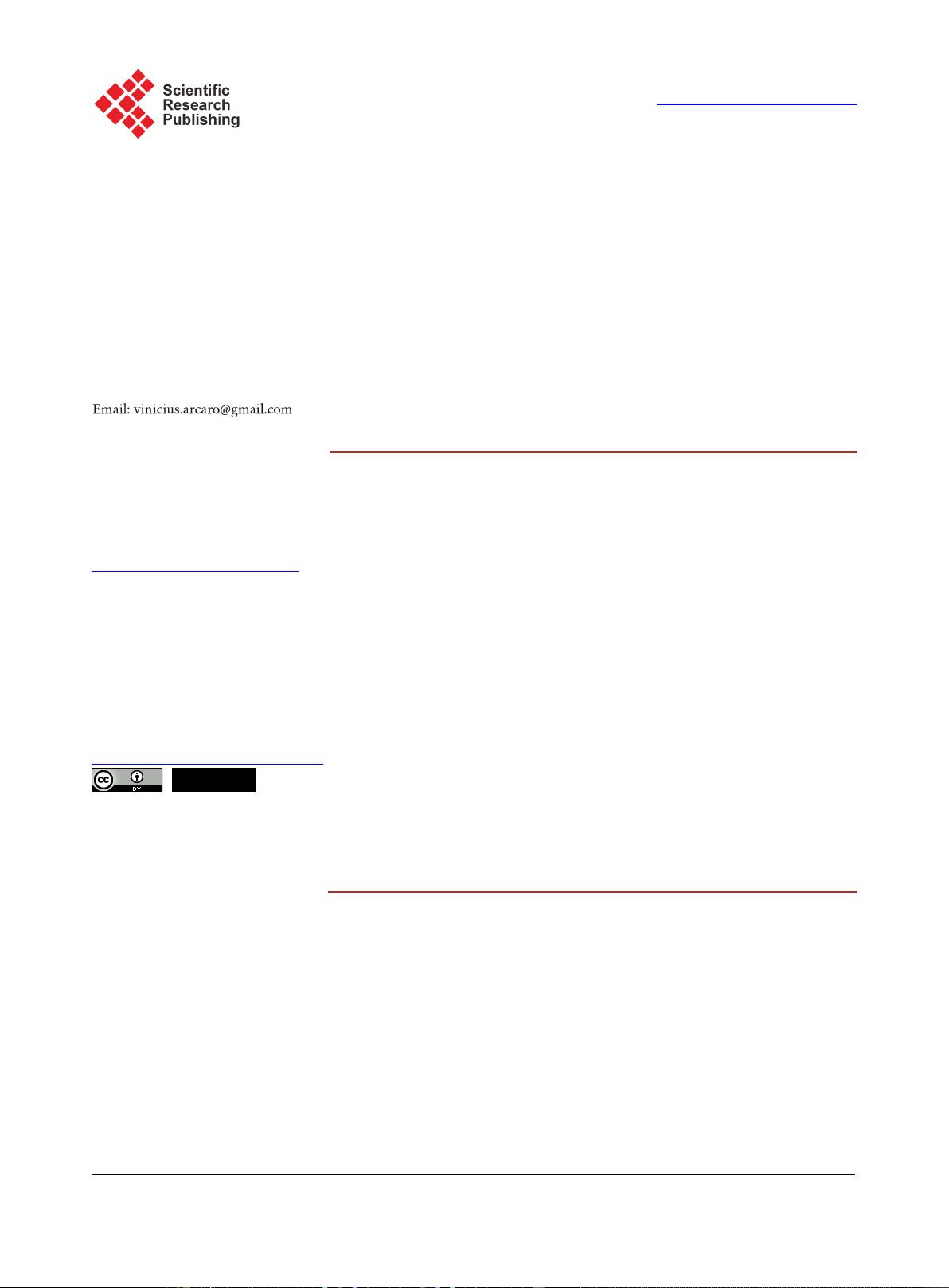
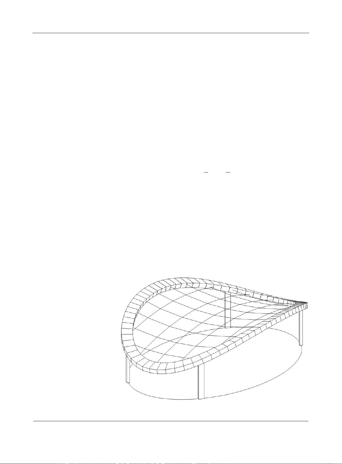
The cable roof network, initially in the form of a hyperbolic paraboloid surface,
is anchored in a ring of reinforced concrete whose axis projects an ellipse in the
horizontal plan. The larger and smaller axes of the ellipse measure 20.00 m and
13.00 m, respectively. The network is formed by an orthogonal mesh 10 by 6,
which is parallel to the ellipse axes. Both end points of the larger axis are 1.75 m
below the surface center, while both end points of the smaller axis are 1.00 m
above the surface center. The center of the surface is 4.50 m above the ground. A
wire rope with diameter of 1 inch (25.4 mm) and composed of galvanized steel
How to cite this paper:
Arcaro, V.F. and
de Almeida
, L.C. (2017)
Practical Aspects
of the Design and Construction of a Small
Cable Roof Structure
.
Open Journal of Civil
Engineering
,
7
, 453-467.
https:
//doi.org/10.4236/ojce.2017.73031
Received:
August 8, 2017
Accepted:
August 29, 2017
Published:
September 1, 2017
Copyright © 201
7 by authors and
Scientific
Research Publishing Inc.
This work is licensed under the Creative
Commons Attribution
International
License (CC BY
4.0).
http://creativecommons.org/licenses/by/4.0/
Open Access
V. F. Arcaro, L. C. de Almeida
DOI:
10.4236/ojce.2017.73031 454
Open Journal of Civil Engineering
wires of high resistance was specified for the cables. Cable clamps were used at
the intersection of two cables and purlins were fixed over the cable clamps in the
direction parallel to the ellipse’s smaller axis. A pre-painted steel sinusoidal sheet
was used for roof cladding. The cross section of the edge ring is rectangular
measuring 1.00 m wide by 0.45 m high. The edge ring axis follows the form of
the hyperbolic paraboloid surface. The ring is sustained by four identical rein-
forced concrete columns with 3.71 m high and rectangular cross section mea-
suring 0.25 m by 0.50 m. The axis of the smaller moment of inertia of the rec-
tangle is tangent to the ellipse equation. The structure is shown in
Figure 1. No-
tice the rotation of the cross section of the edge ring.
2. The Hyperbolic Paraboloid Surface Equation
The hyperbolic paraboloid surface, which is necessary for the description of the
undeformed configuration of the cable network, can be written as:
22
xy
zA B
ab
= +
(1)
The value of
A
is equal to −1.75 m, the value of
B
is equal to 1.00 m, the value
of
a
is equal to 10.00 m and the value of
b
is equal to 6.50 m.
3. Finite Element Discretization of the Structure
The finite element discretization of the structure is shown in Figure 2. The cable
network was discretized with 96 cable elements. Reference [1] describes this
element and explains a procedure to tension the cable network. The edge ring
was discretized with 72 beam elements, of the type often used in the linear anal-
ysis of structures. This element is suitable because small displacements are ex-
pected for the edge ring. The discretized edge ring is defined by a closed poly-
Figure 1. Structure.
V. F. Arcaro, L. C. de Almeida
DOI:
10.4236/ojce.2017.73031 455
Open Journal of Civil Engineering
Figure 2. Structural model.
gonal line, whose vertexes belong to the hyperbolic paraboloid surface. Only one
beam element was used for the discretization of each column. Reference [2] is a
public domain 3D finite element program for the design and analysis of light
structures. The program element library includes cable elements, membrane
element, frame element and spring element. The computer source code written
in Ada95, the executable code for Windows and examples is available for down-
load. The input files used to analyze this structure are included as example
number 2.
Figure 3 shows the node numbering of the structural model. Column 1 is
linked to nodes 6 and 73, column 2 is linked to nodes 30 and 74, column 3 is
linked to nodes 42 and 75 and column 4 is linked to nodes 66 and 76. The con-
nection between the edge ring and the column can obstruct the ring’s rotation
about its axis, favoring the appearance of torsional moment in the ring. To mi-
nimize this torsional moment, the columns were hinged at the ring connection
and clamped at its the base. Moreover, the axis of the smaller moment of inertia
of the column’s cross-section was placed tangentially to the ellipse equation, be-
cause the pinned hypothesis for the connection will not be verified perfectly in
the real structure.
4. Material Specifications
A wire rope with a diameter of 1 inch (25.4 mm) and composed by 37 galvanized
steel wires of high resistance was specified for the cables. The metallic area is
equal to 3.829170 cm
2
, the elastic modulus is equal to 14710 kN/cm
2
, the break
force is equal to 456 kN, and the thermal coefficient is equal to 0.0000115/C.
Reference [3] discusses the benefits of structural cables previously submitted to
tensioning to eliminate the initial lengthening caused by the helical configure-
V. F. Arcaro, L. C. de Almeida
DOI:
10.4236/ojce.2017.73031 456
Open Journal of Civil Engineering
Figure 3. Binding cable connected to the edge ring.
tion of the wires. The specification for the concrete is given by an elastic mod-
ulus equal to 2746 kN/cm
2
, transverse elastic modulus equal to 1144 kN/cm
2
,
and a specific weight equal to 24.5 kN/m
3
.
5. Loading Cases
At the time of the construction, no wind loads guidelines were available for this
roof shape. In the absence of guidelines and considering the characteristics of
the region where the structure was built, an ad hoc estimate for the design wind
loads was a downward pressure of 470 Pa and an upward pressure of 706 Pa. For
the cable network, the wind load was considered acting orthogonal to the
hyperbolic paraboloid surface, which is the undeformed configuration of the ca-
ble network. Reference [4] provides guidelines for loading cases and corres-
ponding safety factors for structural applications of steel cables for buildings.
Notice that a deformed configuration of the cable network does not define a
hyperbolic paraboloid surface. For the edge ring, the load of the lateral wind was
considered acting orthogonal to its faces. The eight loading cases considered for
the design of the structure are shown in
Table 1, where L is the loading case
number, SF is the safety factor for the cable force, ∆T is the temperature change,
(1) is the vertical pressure applied to the cable network due to the permanent or
live load, (2) is the orthogonal pressure applied to the cable network due to the
wind load and (3) is the orthogonal pressure applied to the edge ring due to the
lateral wind load. The direction of the lateral wind is horizontal and is further
determined by an angle specified in degrees in relation to the X-axis.
6. Cable Network
Reference [1] describes the cable element. The cable element has three states:
剩余15页未读,继续阅读
资源评论
weixin_38582909
- 粉丝: 5
- 资源: 975
上传资源 快速赚钱
- 我的内容管理 展开
- 我的资源 快来上传第一个资源
- 我的收益 登录查看自己的收益
- 我的积分 登录查看自己的积分
- 我的C币 登录后查看C币余额
- 我的收藏
- 我的下载
- 下载帮助
安全验证
文档复制为VIP权益,开通VIP直接复制
信息提交成功