没有合适的资源?快使用搜索试试~ 我知道了~
资源推荐
资源详情
资源评论
Unified Modeling Language For Real-Time Systems Design Page 1
Rational Software Corporation
Unified Modeling Language
for Real-Time Systems Design
Introduction
The Unified Modeling Language, or UML, is a third-generation object-oriented modeling
language. It adapts and extends the published works of Grady Booch, Jim Rumbaugh, and
Ivar Jacobson [Booch94, OMT91, OOSE92] and contains improvements and suggestions
made by dozens of others. The UML is being presented to the Object Management Group
in the hope that it will become a standard modeling language for object-oriented
development. Because the UML is meant to be applicable to the modeling of all types of
systems, it applies equally well to real-time systems, client/server, and other kinds of
“standard” software applications. It provides a rich set of notations and promises to be
supported by all major CASE tool vendors.
The purpose of this white paper is to discuss some of the highlights of the UML,
particularly as they apply to the design of real-time systems. This work is based on the
latest drafts of the UML documentation available at the time of writing [UML0.8,
UML0.91]. Because of the depth of these documents, this paper addresses only the most
fundamental elements of the UML but omits many details. For the latest and most
complete information, please see the object technology section of Rational Software
Corporation’s Web site (
http://www.rational.com/ot/uml.html.
An Object-Oriented Approach to Modeling Systems
Structured methods clearly separate data from functions, decreasing their cohesion.
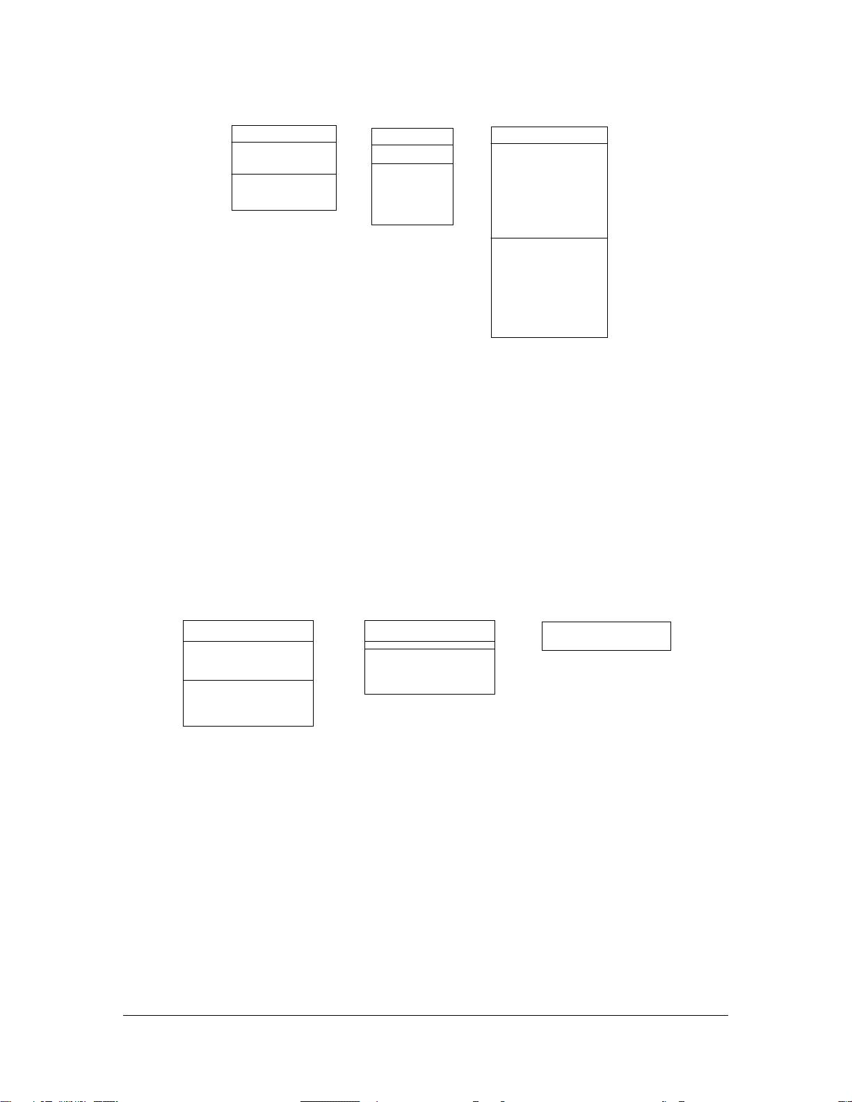
Object-oriented (OO) methods take a different approach. They unify data and the
functions that operate on them into software components called
objects
. In the real-time
world, objects are models of things such as sensors, motors, and communication
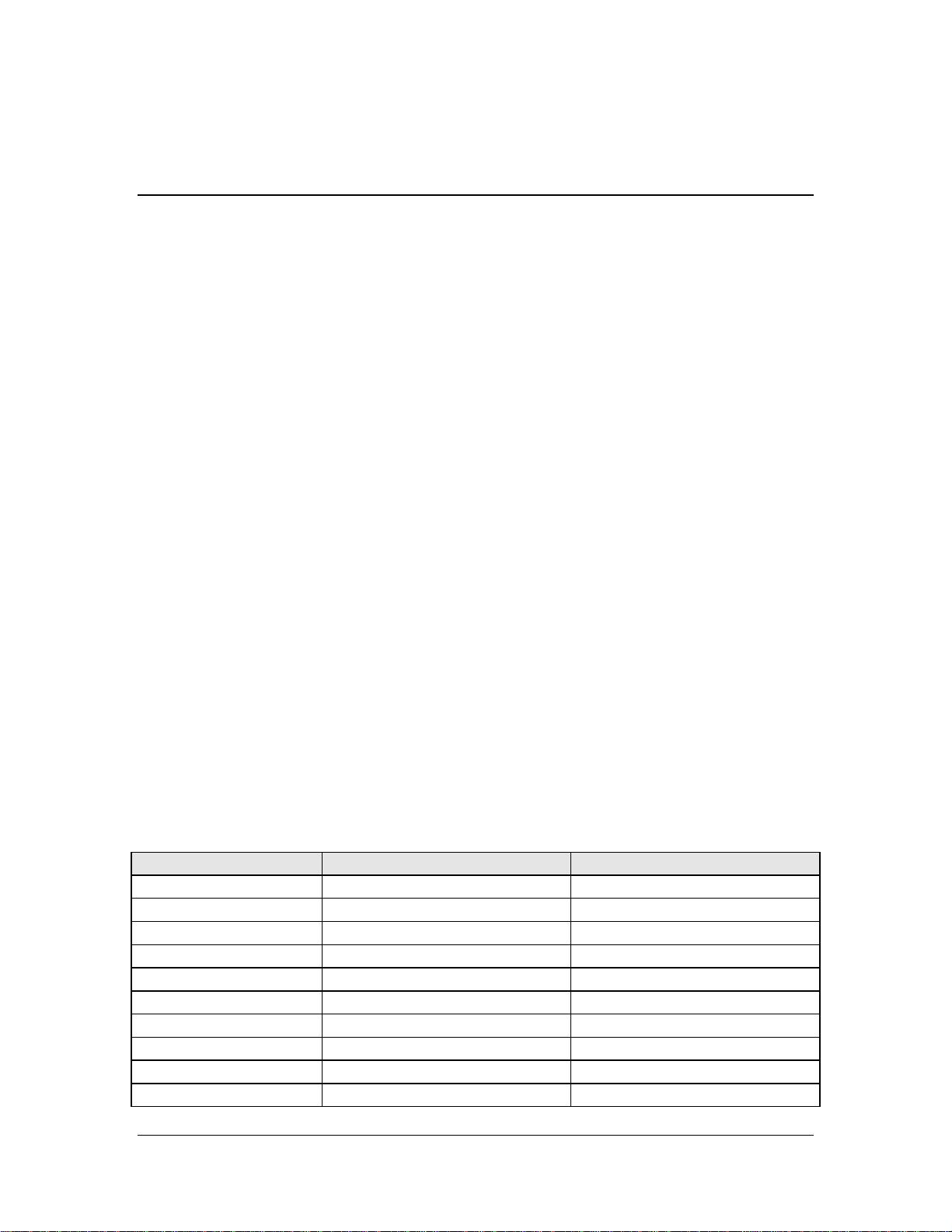
interfaces. The following table provides an informal object-oriented description of these
kinds of objects:
Object Type Data Functions
Temperature Sensor
Temperature Acquire( )
Calibration Constant Set Calibration( )
Stepper Motor
Position Step Forward( )
Step Backward( )
Park( )
Power( )
RS232 Interface
Data to be Transmitted Send Message( )
Data Received Receive Message( )
Unified Modeling Language For Real-Time Systems Design Page 2
Rational Software Corporation
Object Type Data Functions
Baud Rate Set Comm Parameters( )
Parity Pause( )
Stop Bits Start( )
Start Bits Get Error( )
Last Error Clear Error ( )
Because some of the objects in a system can be replicates of one another, it would be
redundant and tedious to specify the data and functions of each. OO methods use the
notion of a
class
to capture, in one place, the
structure
(for example, the common data
fields) and the
behavior
(for example, common functions callable) of such objects.
A class is like a C-language
struct
declaration that contains both data and function
(pointer) fields. Structs are definitions of groups of fields that are closely related. All
variables of the same struct type look alike in that they all have the same fields.
Correspondingly, every object has a definition that is prescribed by its class. But unlike C
structs, which generally define only data fields, an object’s class defines both its data and
its functions in one cohesive structure. Using the UML terminology, the data portion of an
object is defined by a set of
attributes,
and the functional portion of an object is defined by
a set of
operations
.
While every object of a given class has exactly the same structure and behavior
,
each
object is unique in that changes to one do not automatically affect others. For example,
every object of the
Temperature Sensor
class has its own copy of the data items
Temperature
and
Calibration Constant
, as well as its own access to the operations
Acquire
( ) and
Set Calibration
( ).
Structuring data and functions into classes is fundamental to modeling with an OO
approach. Another key principle of object orientation is
encapsulation.
This principle
states that the data portion of an object is accessible only through the functions defined by
the object’s class. Encapsulation makes objects more reliable and safe in that:
•
Users of an object cannot directly affect the state of the object, but rather must go
through a more controlled interface, such as a function call.
•
Developers of an object’s class can make changes to the data portion often with little
or no impact on the users.
Learning to appreciate and efficiently use encapsulation is often the most difficult part of
making the “paradigm shift” that is required when going from a structured method
background to an object-oriented method.
Modeling with UML Diagrams
While tables like those in the previous section provide a convenient way to informally
capture class definitions, the UML goes much further in the kinds of information that can
Unified Modeling Language For Real-Time Systems Design Page 3
Rational Software Corporation
be modeled. The easiest way to describe the various modeling aspects of the UML is
through the notation defined for its various types of diagrams.
The UML distinguishes between the notions of model and diagram
.
A
model
contains all
of the underlying elements of information about a system under consideration and does so
independently of how those elements are visually presented. A
diagram
is a particular
visualization of certain kinds elements from a model and generally exposes only a subset of
those elements’ detailed information. A given model element might exist on multiple
diagrams, but there is but one definition of that element in the underlying model.
This paper introduces the notation and semantics for the following kinds of diagrams
supported in the UML:
•
Class diagram
•
Use-case diagram
•
Interaction diagram
−
Sequence diagram
−
Collaboration diagram
•
State diagram
•
Component diagram
•
Deployment diagram
Each type of diagram captures a different perspective, or view, of the system’s underlying
model. For any of the diagram types, multiple diagrams of that type may exist.
Note that not all of these diagram types have features specifically intended for the
modeling of real-time systems. In particular, interaction, state, and deployment diagrams
have the most to offer in the real-time arena. But for completeness, the following sections
describe the notation and semantics for each of these types of diagrams.
Class Diagram
As with other object-oriented methods, the class diagram is core to a UML model. A class
diagram shows the important abstractions in a system and how they relate to each other.
The primary elements found on class diagrams are class icons and relationship icons.
Classes, Attributes, and Operations
Individual classes are represented in the UML as solid, outline rectangles with one, two,
or three compartments. Figure 1 shows how the classes described in the previous tables
can be represented using the UML class icons. The first compartment is for the name of
the class and is required. The second and third compartments are optional and may be
used to list the attributes and operations defined by the class.
Unified Modeling Language For Real-Time Systems Design Page 4
Rational Software Corporation
Temperature Sensor
temperature
calibration constant
acquire( )
set calibration( )
Stepper Motor
position
step forward( )
step backward( )
park( )
power( )
RS232 Interface
data to be transmitted
data received
baud rate
parity
stop bits
start bits
last error
send message( )
receive message( )
set comm parameters( )
pause( )
start( )
get error( )
clear error( )
Figure 1: Class icons with attribute and operation compartments
While displaying such details for a few specific classes can be useful, showing all class
members for all classes in a model can quickly clutter a class diagram. Such complexity
defeats the purpose for using class diagrams, which is to provide some degree of
abstraction above the vast underlying details found in any nontrivial model. This is why the
UML allows a class icon to suppress displaying any or all of its members. This principle is
key to the UML: Diagrams do not generally expose the total contents of a model, but
rather only some subset of the model’s details.
Thus, all of the icons shown in Figure 2 are valid representations for the class
Temperature Sensor—they are merely different views of the underlying model.
Temperature Sensor
temperature
calibration constant
acquire( )
set calibration( )
Temperature Sensor
acquire( )
set calibration( )
Temperature Sensor
Figure 2: Multiple views of the same underlying class model
Relationships
Stand-alone classes provide only so much value in and of themselves. Most classes in a
system will be related to other classes so that their corresponding objects can collaborate
to accomplish more complex functionality. So in addition to classes, attributes, and
operations, class diagrams also depict various types of
relationships
that exist between
dependent classes.
剩余19页未读,继续阅读
资源评论
- kingdy74022011-10-23不说了,打不开
- JhonSmithk2011-11-27好像不太完整
sxa3g
- 粉丝: 2
- 资源: 59
上传资源 快速赚钱
- 我的内容管理 展开
- 我的资源 快来上传第一个资源
- 我的收益 登录查看自己的收益
- 我的积分 登录查看自己的积分
- 我的C币 登录后查看C币余额
- 我的收藏
- 我的下载
- 下载帮助
最新资源
- mmexport1713192608513.mp4
- 斯特林V4发动机 斯特林V4发动机
- 基于C实现的N阶数字正方形 ;N阶数字三角形;N阶数字递减三角形;乘法表
- 基于分水岭算法的图像分割的python源码(课程设计).zip
- 基于Java 实现的二进制十进制之间的相互转换
- Pytorch实现基于卷积神经网络的面部表情识别项目源码+数据集+全部资料(毕业设计).zip
- Pytorch实现基于深度学习卷积神经网络的面部表情识别项目源码+面部表情数据集(人脸面部表情识别项目).zip
- 淘金小游戏助手.apk
- 基于卷积神经网络的人脸面部表情识别项目源码+面部表情数据集+训练好的模型(人脸面部表情识别项目).zip
- 深度学习基于卷积神经网络的人脸面部表情识别项目源码+面部表情数据集+训练好的模型(人脸面部表情识别项目).zip
资源上传下载、课程学习等过程中有任何疑问或建议,欢迎提出宝贵意见哦~我们会及时处理!
点击此处反馈
安全验证
文档复制为VIP权益,开通VIP直接复制
信息提交成功