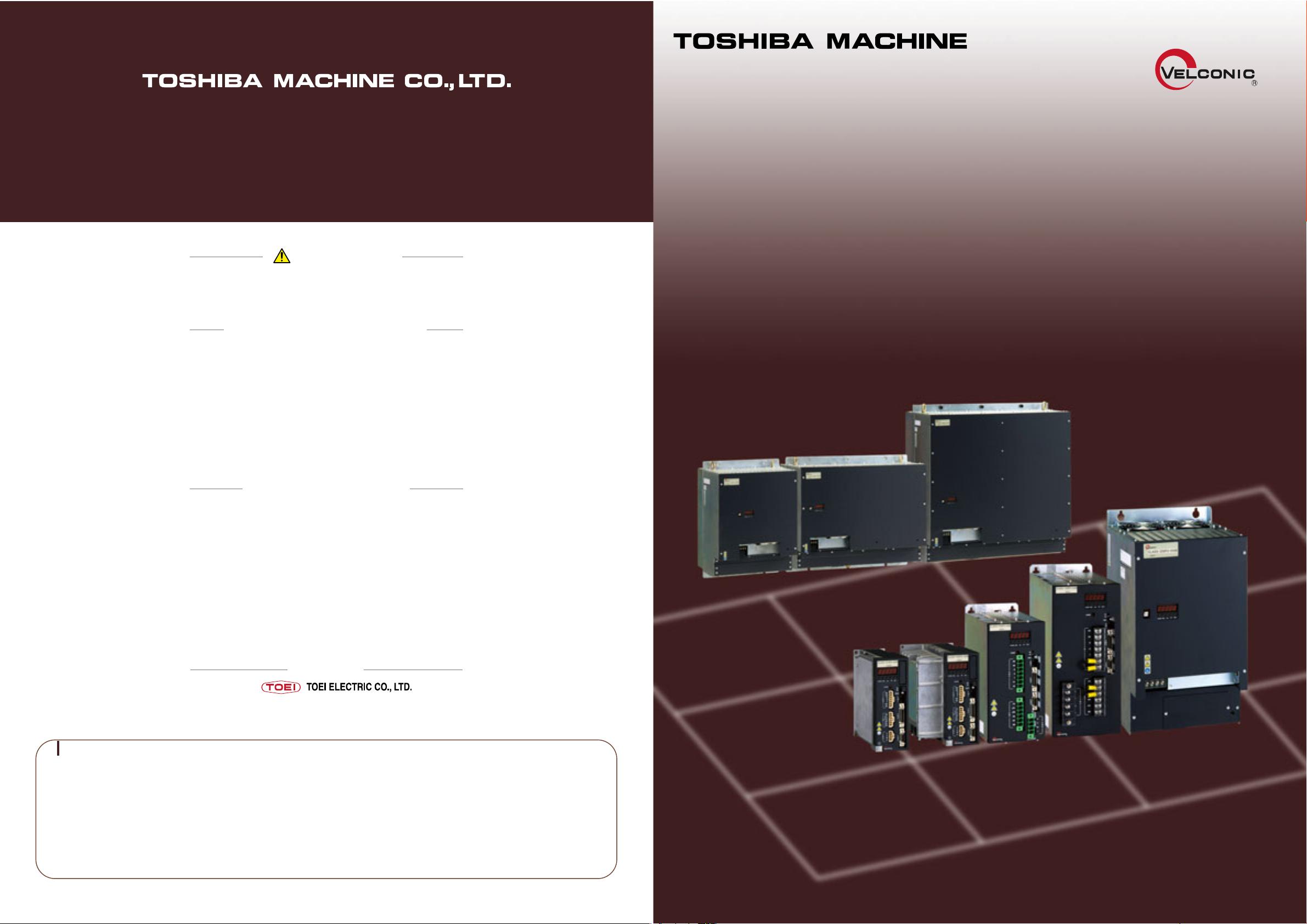
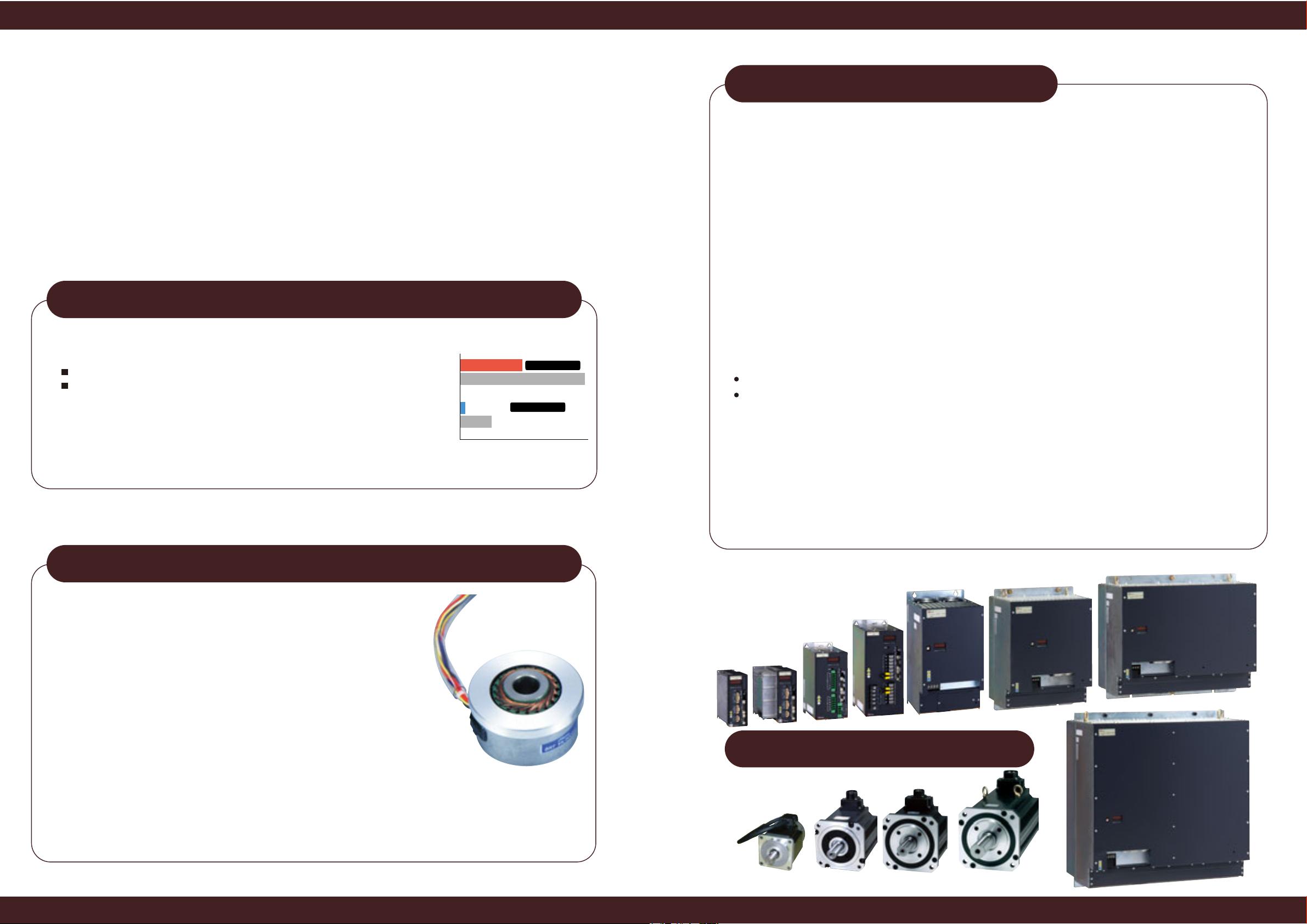
X Series Standard Servo Amplifier X Series Standard Servo Amplifier
6 7
Set valueSet value
Set value Set valueSet value
Ampere command voltage
Speed command voltageSpeed command voltage
Machine speed lower digits
Motor speed
Pulse command upper digits
Pulse command lower digits
Machine speed upper digits
Fin temperature
PN voltage
Deviation lower digits
Check display
area
General input/output
Option input
Alarm
Alarm history
Software version
Option output
Option status
Set value
Set value
Set value
Set value
Set value
Motor code
Resolver cable length
Electronic gear (numerator)
Electronic gear (denominator)
Control mode
Set value
Set value
Set value
Set value
Tuning parameter
area (auto tuning)
Motor angle (mechanicalangle)
Axis number
Power unit status
Warning output
Servo lock shortage condition
Tuning mode Target loop gain Load inertia
Changeover speed
loop integral gain
Changeover
load inertia
Changeover speed
loop gain
MODE
MODE
MODE
MODE
MODE
Speed command zero adjustmentSpeed command zero adjustment
Speed command scale
Ampere command zero adjustment
Current command scale
Set value
Set value
Analog output 2 scale
Analog output 2 selection
Filter tuning
SEL
Double-click [MODE].
Command value lower digits
Deviation upper digits
Command value upper digits
Present value upper digits
Present value lower digits
No. of sensor pulses - lower digits
No. of sensor pulses - upper digits
Motor phase value (electrical angle)
Absorption ratio
Electronic thermal value
Effective load factor
Motor ampere
Status
display
area
User
parameter
area
Adjustment
area
5sec.
Set value
AMOUT output scale
Derated
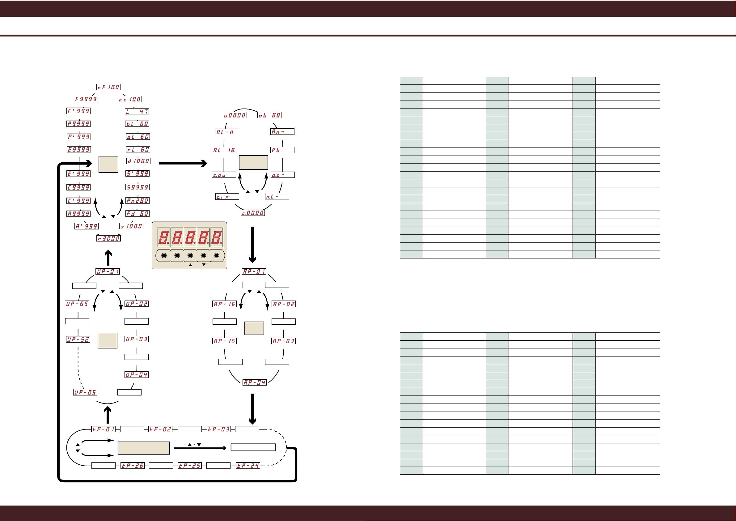
Parameter Setting
Display and Operation
No. Parameter name No. Parameter name No. Parameter name
UP-01 Control mode (*1)
UP-22
Capacity of external
reverse-current absorption resistor
UP-43 UP-65
Decimal point position of display
DERATED
UP-02 Motor code
UP-23
UP-44 Sequence input reversal
UP-03 Resolver cable length
UP-24 Feedrate 1
UP-45 Sequence output reversal
UP-04
Numerator of electronic gear
UP-25 Feedrate 2
UP-46
Sequence input/output selection
UP-05
Denominator of electronic gear
UP-26 Feedrate 3
UP-47 In-position timer
UP-06 Home point shift value
UP-27 Feedrate 4
UP-48 Electronic gear factor
UP-07 In-position length
UP-28 Stop detection speed
UP-49 VMOUT output selection
UP-08 Ampere limit value
UP-29 Coincident speed
UP-50 VMOUT output scale
UP-09 Soft start acceleration time
UP-30
Width of coincident speed detection
UP-51 AMOUT output selection
UP-10 Soft start deceleration time
UP-31 Motor test speed
UP-52 AMOUT output scale
UP-11
S-type acceleration/deceleration time
UP-32 Analog I/O selection
UP-53
Split count of position feedback pulse
(upper-digit)
UP-12 ABS mode
UP-33 Load factor time constant
UP-54
Split count of position feedback pulse
(lower-digit)
UP-13 Holding brake operation
UP-34 Limit changeover type
UP-55
Setting of VLBus-V operation check (*5)
UP-14 Brake ON speed (*2)
UP-35 Speed limit value
UP-56
Setting of rotation coordinate system
(upper-digit) (*5)
UP-15 Analog command polarity
UP-36
Forward drive current limit value
UP-57
Setting of rotation coordinate system
(lower-digit) (*5)
UP-16 Pulse command type
UP-37
Forward rotation absorption
current limit value
UP-58 Selection of LS function (*5)
UP-17 Pulse output type
UP-38
Reverse drive current limit value
UP-59
Selection of LS function reversal (*5)
UP-18 Differential output type (*3)
UP-39
Reverse rotation absorption
current limit value
UP-60 Home point stop method (*5)
UP-19 Position control polarity
UP-40
Width of drive/absorption detection
UP-61
Monitor type of analog input (*5)
UP-20 Draw factor
UP-41
Numerator of display magnification
UP-62
Permission/prohibition of level 4 alarm
detection (*5)
UP-21
External reverse-current
absorption resistance
UP-42
Denominator of display magnification
UP-63 Overrun stop time (*5)
UP-64 Draw value
Common power supply mode (*4)
*1: Available only when the VLBus-V specification is selected.
*2: Available only when the tiny positioner specification is selected.
*3: Available only when the VLBus-V and tiny positioner specifications are selected.
No. Alarm message No. Alarm message No. Alarm message
AL01
Overcurrent (OC) Instant thermal (POL)
Overvoltage (OV)
PN voltage drop (PNLV) Overspeed (OSPD)
AL04
Main power input error (ACINF) Deviation counter over (FULL)
AL05
Charging resistor overheat (CROH)
AL06
Resolver cable breakage (RELV) Resolver ABS breakage (ACN)
AL07
AL08
Servo amplifier overheat (SOH) Option alarm (OPALM)
AL09
Reverse-current absorption resistor
overheat (RGOH)
Parameter setting error (CERR)
AL10
Reverse-current absorption error (RGST)
Resolver ABS error (AEERR)
AL11
Instant thermal 2 (BAOL) Link error (LINKERR)
AL12
Undefined
Command value over (CONDV)
AL13
ABS battery voltage drop (BLV)
ABS home point invalid (CLD)
AL14
Brake error (BERR)
Overcurrent detection (OCS)
Speed amplifier saturation (VAS)
Motor overload (MOL)
AL18
AL19
AL20
AL21
AL22
AL23
AL24
AL25
AL26
AL27
AL28 (*1)
AL32
AL33
Present value over (ACTOV)
Home point unsaved error (MZE)
AL29 (*1)
AL30 (*1)
AL34 (*3)
AL35 (*3)
AL36
AL37 (*2)
ABS battery alarm (BAL)
AL38 (*3)
AL39 (*2)
AL40
AL41
AL42
AL43
AL44
AL45
AL46
AL47
AL48
AL49
AL50 (*2)
AL51 (*2)
AL52 (*2)
AL02
AL03
AL15
AL16
AL17
Soft limit + over (SOTP)
Soft limit - over (SOTM)
Power status error (POWFAIL)
Resolver phase error (RESERR)
Resolver ABS phase error (ABSE)
Overrun (OVTR)
Limit error (LIMERR)
Encoder breakage (EREE)
Encoder communication error (ETER)
Encoder backup error (EBACK)
Encoder checksum error (ECKER)
Encoder battery alarm (EBAL)
Encoder ABS phase error (EABSE)
Encoder overspeed (EOSPD)
Encoder interrupt error (EWER)
Encoder initialize error (EINIT)
Data input error (DATAE)
Present value undecided error (ACTE)
Communication error (COM)
Coordinate counter over (COVER)
Encoder sensor phase error (PHSERR)
ABS battery cable breakage (ABT)
*1: Specify the speed control, current control, speed/current/position control, direct feed or draw control mode. For the VLBus-V specification, "31" is
predetermined.
*2: Specify the operation speed of the holding brake.
*3: Select the differential output function and content (i.e., pulse output, display output, ABS present value, command pulse, or draw pulse).
*4: Specify when you wish to use the main circuit DC power in common.
*5: Only in VLBus-V specifications.
User parameters
Alarm code table
On the display & operation unit, you can perform display of servo motor operation status, check of sequence or alarm,
adjustment of each control command value, setting of user parameters including selection of control mode and resolution, and
setting of turning parameters for servo adjustment.
Specify the servo amplifier parameters according to the operation characteristic of the machine. For the electronic gear,
setting of a fraction is possible, and the acceleration/deceleration comes with two types; S-type acceleration/deceleration and
linear acceleration/deceleration. Also, joint use of holding and dynamic brakes is possible.
The self-diagnosis function is provided, and the content of a trouble is displayed by code. The alarm history function records
the order of alarm generation if two or more alarms have occurred at the same time, thus the maintenance can be facilitated.
Hierarchal operation


评论0
最新资源