没有合适的资源?快使用搜索试试~ 我知道了~
MAX96705 datasheet
需积分: 50 54 下载量 49 浏览量
2019-03-05
14:22:47
上传
评论 2
收藏 2.16MB PDF 举报
温馨提示
试读
83页
MAX96705GTJ为车规级小尺寸串行器,TQFN32封装,特别适合于汽车摄像应用的特性。其功能和引脚与MAX9271兼容。高带宽模式下,对于12位线性或组合HDR数据类型,并行时钟最大为116MHz,允许设置串行器、解串器和摄像寄存器独立于视频时钟。为驱动较长电缆,IC具有可编程预加重/去加重。串行输出提供可编程扩频。串行输出满足ISO 10605和IEC 61000-4-2 ESD标准。核心电源供电范围为1.7V至1.9V,I/O电源范围为1.7V至3.6V。
资源推荐
资源详情
资源评论
General Description
The MAX96705 is a compact serializer with features
especially suited for automotive camera applications. It is
function and pin compatible with the MAX9271. In high-
bandwidth mode, the parallel-clock maximum is 116MHz
for 12-bit linear or combined HDR data types.
The embedded control channel operates at 9.6kbps to
1Mbps in UART, I
2
C, and mixed UART/I
2
C modes, allow-
ing programming of serializer, deserializer, and camera
registers independent of video timing.
For driving longer cables, the IC has programmable
pre/deemphasis. Programmable spread spectrum is
available on the serial output. The serial output meets
ISO 10605 and IEC 61000-4-2 ESD standards. The core
supply range is 1.7V to 1.9V, and the I/O supply range is
1.7V to 3.6V.
The MAX96705 is available in a 32-pin (5mm x 5mm)
TQFN package with 0.5mm lead pitch, and operates over
the -40°C to +115°C temperature range.
Applications
● Automotive Camera Applications
Benets and Features
● Ideal for Safety Camera Applications
• Works with Low-Cost 50Ω Coax (100Ω STP) Cables
• Error Detection of Video/Control Data
• High-Immunity Mode for Robust Control-Channel
EMC Tolerance
• Retransmission of Control Data Upon Error
Detection
• Best-in-Class Supply Current: 93mA (max)
• Pre/Deemphasis Allows 15m Cable at Full Speed
• 32-Pin (5mm x 5mm) TQFN Package with 0.5mm
Lead Pitch
● High-Speed Data Serialization for Megapixel
Cameras
• Up to 1.74Gbps Serial-Bit Rate
• 12.5MHz to 87MHz x 14 Bit + H/V Data
• 36.66MHz to 116MHz x 12-Bit + H/V Data
(through Internal Encoding)
● Multiple Modes for System Flexibility
• 9.6kbps to 1Mbps Control Channel in UART, I
2
C
(with Clock Stretch), or UART-to-I
2
C Modes
• Crosspoint Switch Accepts Any Input Bitmap
• Modes for Encoded VSYNC and HSYNC
● Reduces EMI and Shielding Requirements
• Programmable Output Spread Spectrum
• Tracks Spread Spectrum Applied at the Parallel
Input
• 1.7V to 3.6V I/O Supply
● Peripheral Features for Camera Power-Up and
Verification
• Built-In PRBS Generator for BER Testing
• Dedicated GPO for Camera Frame-Sync Trigger
and Other Uses
• Remote/Local Wake-Up from Sleep Mode
● Meets AEC-Q100 Automotive Specification
• -40°C to +115°C Operating Temperature
• ±8kV Contact and ±15kV Air IEC 61000-4-2 and
ISO 10605 ESD Protection
Ordering Information appears at end of data sheet.
19-8434; Rev 1; 2/17
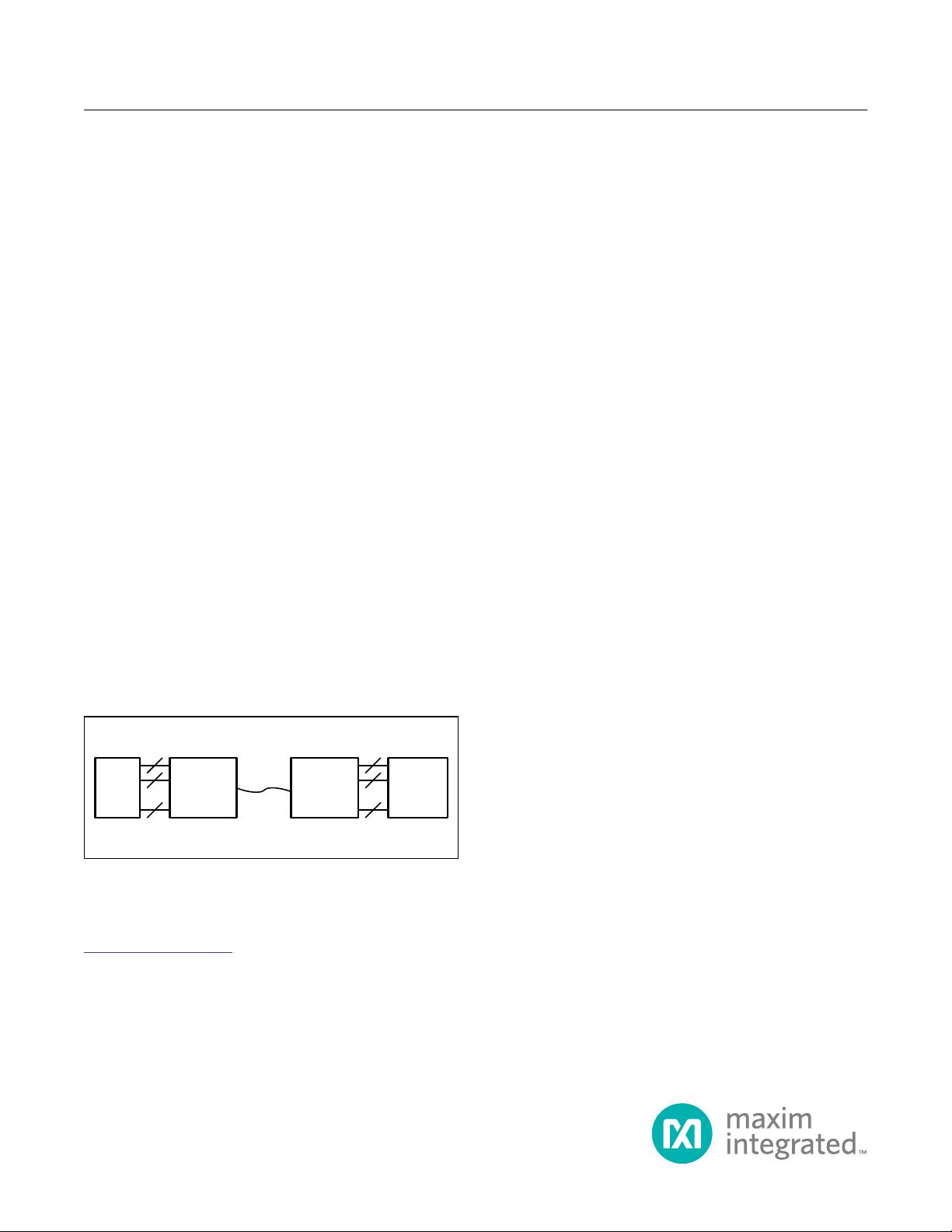
CAM MAX96705 MAX96706
VIDEO
I
2
C
GPU
VIDEO
I
2
C
Simplied Block Diagram
MAX96705 16-Bit GMSL Serializer with High-Immunity/
Bandwidth Mode and Coax/STP Cable Drive
EVALUATION KIT AVAILABLE
General Description ............................................................................ 1
Applications .................................................................................. 1
Benefits and Features .......................................................................... 1
Simplified Block Diagram........................................................................ 1
Absolute Maximum Ratings ...................................................................... 6
Package Information ........................................................................... 6
32-Pin TQFN-EP.............................................................................6
DC Electrical Characteristics ..................................................................... 7
AC Electrical Characteristics . . . . . . . . . . . . . . . . . . . . . . . . . . . . . . . . . . . . . . . . . . . . . . . . . . . . . . . . . . . . . . . . . . . . 10
Typical Operating Characteristics ................................................................ 13
Pin Configuration ............................................................................. 15
Pin Description ............................................................................... 15
Functional Block Diagram ...................................................................... 18
Detailed Description........................................................................... 23
Serial Link Signaling and Data Format ...........................................................23
Operating Modes .........................................................................23
Video/Configuration Link ...................................................................23
Single/Double Mode.......................................................................24
HS/VS Encoding .........................................................................24
Error Detection...........................................................................24
Bus Widths ..............................................................................24
Control Channel and Register Programming ......................................................28
Forward Control Channel...................................................................28
Reverse Control Channel...................................................................28
UART Interface ..........................................................................28
I
2
C Interface.............................................................................28
Remote-End Operation ....................................................................28
Clock-Stretch Timing ......................................................................28
Packet-Based I
2
C ...........................................................................28
Packet Protocol Summary ..................................................................29
Control-Channel Error Detection and Packet Retransmission ......................................29
GPO/GPI Control ...........................................................................29
Spread Spectrum ...........................................................................29
Cable Type Configuration .....................................................................29
Crossbar Switch ............................................................................29
Video Timing Generator ......................................................................29
Shutdown/Sleep Modes ......................................................................31
MAX96705 16-Bit GMSL Serializer with High-Immunity/
Bandwidth Mode and Coax/STP Cable Drive
www.maximintegrated.com
Maxim Integrated
│
2
TABLE OF CONTENTS
Configuration Link ........................................................................31
Serialization Disable ......................................................................31
Sleep Mode .............................................................................31
Power-Down Mode........................................................................32
Link Startup Procedure .......................................................................32
Register Map ................................................................................ 33
GMSL Register Map .........................................................................33
Applications Information........................................................................ 69
Parallel Interface ............................................................................69
Bus Data Width ..........................................................................69
Bus Data Rates ..........................................................................69
Crossbar-Switch Programming ..............................................................70
Recommended Crossbar-Switch Program Procedure ............................................70
Timing-Generator Programming ................................................................73
Double-Mode Alignment ......................................................................73
External High/Low Signal ..................................................................73
Align from HS or DE ......................................................................73
Control-Channel Interfaces....................................................................73
I
2
C ....................................................................................73
I
2
C Bit Rate .............................................................................73
Software Programming of Device Addresses ...................................................74
I
2
C Address Translation....................................................................74
Configuration Blocking.....................................................................74
Cascaded/Parallel Devices .................................................................74
UART ..................................................................................74
Base Mode ..............................................................................74
UART Timing ............................................................................74
UART-to-I
2
C Conversion ...................................................................76
UART Bypass Mode ......................................................................77
Device Address ..........................................................................77
Spread Spectrum ...........................................................................77
Manual Programming of the Spread-Spectrum Divider ..............................................77
Equation: ...............................................................................77
Board Layout ...............................................................................78
Power-Supply Circuits and Bypassing.........................................................78
High-Frequency Signals....................................................................78
ESD Protection .............................................................................78
MAX96705 16-Bit GMSL Serializer with High-Immunity/
Bandwidth Mode and Coax/STP Cable Drive
www.maximintegrated.com
Maxim Integrated
│
3
TABLE OF CONTENTS
(
CONTINUED
)
Compatibility with Other GMSL Devices .........................................................79
Device Configuration and Component Selection . . . . . . . . . . . . . . . . . . . . . . . . . . . . . . . . . . . . . . . . . . . . . . . . . . . 79
Internal Input Pulldowns....................................................................79
Three-Level Configuration Inputs ............................................................79
I
2
C/UART Pullup Resistors .................................................................80
AC-Coupling Capacitors ...................................................................80
Cables and Connectors ....................................................................80
PRBS.....................................................................................80
GPI/GPO ..................................................................................80
Fast Detection of Loss-of-Lock ..............................................................81
Providing a Frame Sync (Camera Applications) .................................................81
Entering/Exiting Sleep Mode ..................................................................81
Typical Application Circuits ..................................................................... 82
Ordering Information .......................................................................... 82
Revision History .............................................................................. 83
Figure 1. Serial-Output Parameters............................................................... 18
Figure 2. Output Waveforms at OUT+, OUT-........................................................ 19
Figure 3. Single-Ended Output Template .......................................................... 19
Figure 4. Worst-Case Pattern Input ............................................................... 19
Figure 5. Parallel Clock Input Requirements ........................................................ 19
Figure 6. I
2
C Timing Parameters ................................................................. 20
Figure 7. Differential Output Template ............................................................. 20
Figure 8. Input Setup and Hold Times ............................................................. 21
Figure 9. GPI-to-GPO Delay .................................................................... 21
Figure 10. Serializer Delay...................................................................... 22
Figure 11. Link Startup Time .................................................................... 22
Figure 12. Power-Up Delay ..................................................................... 23
Figure 13. 24-Bit Mode Serial-Data Format......................................................... 25
Figure 14. 27-Bit High-Bandwidth Mode Serial-Data Format ........................................... 26
Figure 15. 32-Bit Mode Serial-Data Format......................................................... 27
Figure 16. Coax Connection .................................................................... 29
Figure 17. Crossbar Switch Dataflow .............................................................. 30
Figure 18. Sync-Signal Format For Video-Timing Generation .......................................... 30
Figure 19. State Diagram ....................................................................... 31
Figure 20. Crossbar-Switch Default Mapping ....................................................... 72
MAX96705 16-Bit GMSL Serializer with High-Immunity/
Bandwidth Mode and Coax/STP Cable Drive
www.maximintegrated.com
Maxim Integrated
│
4
LIST OF FIGURES
TABLE OF CONTENTS
(
CONTINUED
)
Figure 21. GMSL-UART Data Format for Base Mode ................................................. 75
Figure 22. GMSL-UART Protocol for Base Mode .................................................... 75
Figure 23. SYNC Byte (0x79).................................................................... 75
Figure 24. ACK Byte (0xC3)..................................................................... 75
Figure 25. Format Conversion Between GMSL UART and I
2
C with Register Address (I2CMETHOD = 0)........ 76
Figure 26. Format Conversion Between GMSL UART and I
2
C with Register Address (I2CMETHOD = 1) ........ 76
Figure 27. Human Body Model ESD Test Circuit ..................................................... 78
Figure 28. IEC 61000-4-2 Contact Discharge ESD Test Circuit ......................................... 78
Figure 29. ISO 10605 Contact Discharge ESD Test Circuit ............................................ 78
Table 1. Reverse Control-Channel Modes.......................................................... 28
Table 2. Link-Startup Procedure ................................................................. 31
Table 3. Input Data-Width Selection .............................................................. 68
Table 4. Data-Rate Selection.................................................................... 68
Table 5. Crossbar Output to Serial Link Map (D23:0) ................................................. 69
Table 6. Crossbar Output to Serial Link Map (D31:24 and Special Packets) ............................... 70
Table 7. Legend .............................................................................. 71
Table 8. Timing-Generator Parameter Restrictions ................................................... 72
Table 9. Output Spread ........................................................................ 76
Table 10. Spread Limitations .................................................................... 76
Table 11. Modulation Coefficients and Maximum SDIV Settings ........................................ 77
Table 12. Feature Compatibility . . . . . . . . . . . . . . . . . . . . . . . . . . . . . . . . . . . . . . . . . . . . . . . . . . . . . . . . . . . . . . . . . . 78
Table 13. Three-Level Configuration Input Map ..................................................... 79
Table 14. Suggested Connectors and Cables for GMSL............................................... 79
MAX96705 16-Bit GMSL Serializer with High-Immunity/
Bandwidth Mode and Coax/STP Cable Drive
www.maximintegrated.com
Maxim Integrated
│
5
LIST OF TABLES
LIST OF FIGURES
(
CONTINUED
)
剩余82页未读,继续阅读
资源评论
qq_41101825
- 粉丝: 0
- 资源: 2
上传资源 快速赚钱
- 我的内容管理 展开
- 我的资源 快来上传第一个资源
- 我的收益 登录查看自己的收益
- 我的积分 登录查看自己的积分
- 我的C币 登录后查看C币余额
- 我的收藏
- 我的下载
- 下载帮助
安全验证
文档复制为VIP权益,开通VIP直接复制
信息提交成功