没有合适的资源?快使用搜索试试~ 我知道了~
AVR资料-atmega2560
4星 · 超过85%的资源 需积分: 36 72 下载量 40 浏览量
2012-10-14
09:02:46
上传
评论 1
收藏 2.91MB PDF 举报
温馨提示
试读
407页
AVR单片机是1997年由ATMEL公司研发出的增强型内置Flash的RISC(Reduced Instruction Set CPU) 精简指令集高速8位单片机。AVR的单片机可以广泛应用于计算机外部设备、工业实时控制、仪器仪表、通讯设备、家用电器等各个领域。
资源推荐
资源详情
资源评论
2549A–AVR–03/05
Features
• High Performance, Low Power AVR
®
8-Bit Microcontroller
• Advanced RISC Architecture
– 135 Powerful Instructions – Most Single Clock Cycle Execution
– 32 x 8 General Purpose Working Registers
– Fully Static Operation
– Up to 16 MIPS Throughput at 16 MHz
– On-Chip 2-cycle Multiplier
• Non-volatile Program and Data Memories
– 64K/128K/256K Bytes of In-System Self-Programmable Flash
Endurance: 10,000 Write/Erase Cycles
– Optional Boot Code Section with Independent Lock Bits
In-System Programming by On-chip Boot Program
True Read-While-Write Operation
– 4K Bytes EEPROM
Endurance: 100,000 Write/Erase Cycles
– 8K Bytes Internal SRAM
– Up to 64K Bytes Optional External Memory Space
– Programming Lock for Software Security
• JTAG (IEEE std. 1149.1 compliant) Interface
– Boundary-scan Capabilities According to the JTAG Standard
– Extensive On-chip Debug Support
– Programming of Flash, EEPROM, Fuses, and Lock Bits through the JTAG Interface
• Peripheral Features
– Two 8-bit Timer/Counters with Separate Prescaler and Compare Mode
– Four 16-bit Timer/Counter with Separate Prescaler, Compare- and Capture Mode
– Real Time Counter with Separate Oscillator
– Four 8-bit PWM Channels
– Six/Twelve PWM Channels with Programmable Resolution from 2 to 16 Bits
(ATmega1281/2561, ATmega640/1280/2560)
– Output Compare Modulator
– 8/16-channel, 10-bit ADC
– Two/Four Programmable Serial USART (ATmega1281/2561,ATmega640/1280/2560)
– Master/Slave SPI Serial Interface
– Byte Oriented 2-wire Serial Interface
– Programmable Watchdog Timer with Separate On-chip Oscillator
– On-chip Analog Comparator
– Interrupt and Wake-up on Pin Change
• Special Microcontroller Features
– Power-on Reset and Programmable Brown-out Detection
– Internal Calibrated Oscillator
– External and Internal Interrupt Sources
– Six Sleep Modes: Idle, ADC Noise Reduction, Power-save, Power-down, Standby,
and Extended Standby
• I/O and Packages
– 51/86 Programmable I/O Lines (ATmega1281/2561, ATmega640/1280/2560)
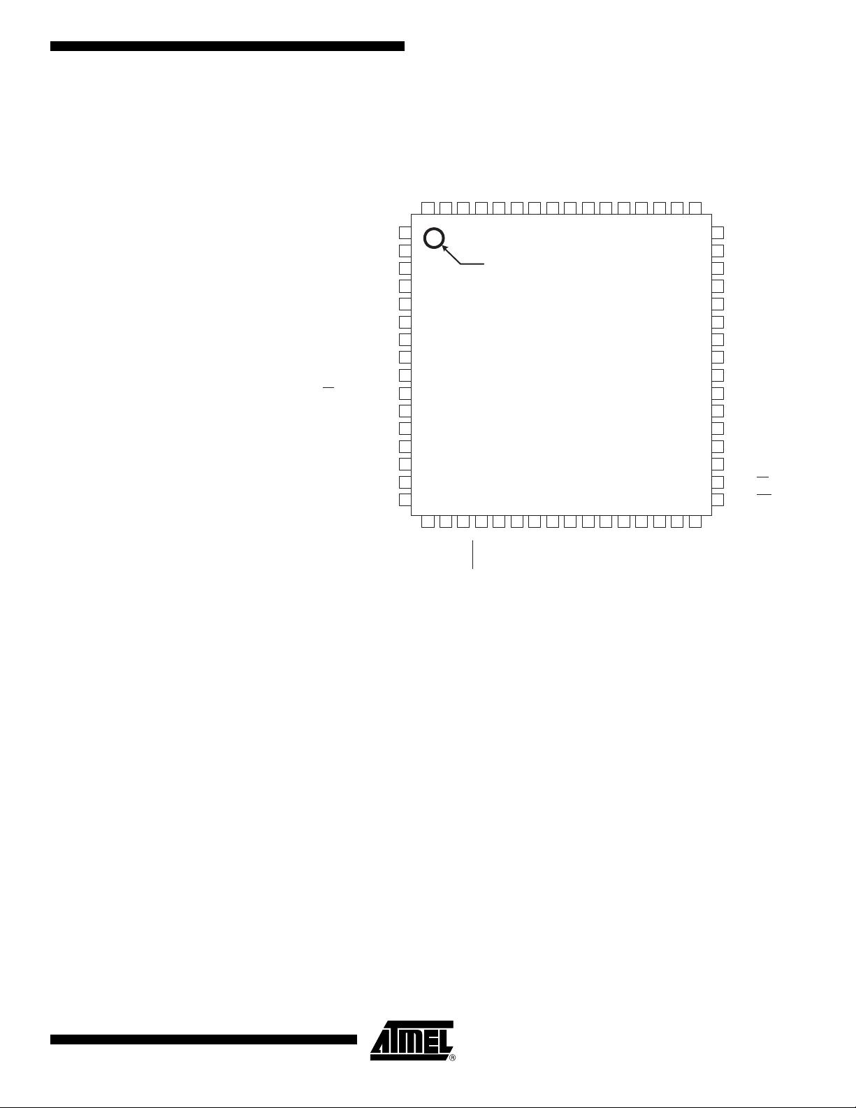
– 64-lead (ATmega1281/2561)
– 100-lead (ATmega640/1280/2560)
– 100-lead TQFP (64-lead TQFP Option)
• Temperature Range:
–-40
°C to 85°C Industrial
• Speed Grade:
– ATmega1281/2561V/ATmega640/1280/2560V:
0 - 4 MHz @ 1.8 - 5.5V, 0 - 8 MHz @ 2.7 - 5.5V
– ATmega640/1280/1281/2560/2561:
0 - 8 MHz @ 2.7 - 5.5V, 0 - 16 MHz @ 4.5 - 5.5V
8-bit
Microcontroller
with 256K Bytes
In-System
Programmable
Flash
ATmega1281/25
61/V
ATmega640/128
0/2560/V
Advance
Information
2
ATmega640/1280/1281/2560/2561
2549A–AVR–03/05
Pin Configurations Figure 1. Pinout ATmega640/1280/2560
GND
VCC
PA0 (AD0)
PA1 (AD1)
PA2 (AD2)
PA3 (AD3)
PA4 (AD4)
PA5 (AD5)
PA6 (AD6)
PA7 (AD7)
PG2 (ALE)
AVCC
GND
AREF
PF0 (ADC0)
PF1 (ADC1)
PF2 (ADC2)
PF3 (ADC3)
PF4 (ADC4/TCK)
PF5 (ADC5/TMS)
PF6 (ADC6/TDO)
PF7 (ADC7/TDI)
ATmega640/1280/2560
100
99 98 97 96 95 94 93 92 91 90 89 88 87 86 85 84 83 82 81 80 79 78 77 76
1
2
3
4
5
6
7
8
9
10
11
12
13
14
15
16
17
18
19
20
21
22
23
24
25
75
74
73
72
71
70
69
68
67
66
65
64
63
62
61
60
59
58
57
56
55
54
53
52
51
26 28 29 3127 3630 32 35 3733 34 38 39 40 41 42 43 44 45 46 47 48 49 50
PK0 (ADC8/PCINT16)
PK1 (ADC
9/PCIN
T17)
PK2 (ADC10/PCINT18)
PK3 (ADC11/PCINT1
9)
PK4 (ADC12/PCINT20)
PK5 (ADC13/PCINT21)
PK6 (ADC14/PCI
NT22)
PK7 (ADC15/PCI
NT23)
(OC2B) PH6
(TOSC2) PG3
(TOSC1) P
G4
RESET
(T4) PH7
(ICP4) PL0
VCC
GND
XTAL2
XTAL1
PL6
PL7
GND
VCC
(OC0B) PG5
VCC
GND
(RXD2) PH0
(TXD2) PH1
(XCK2) PH2
(OC4A) PH3
(OC4B) PH4
(OC4C) PH5
(RXD0/PCINT8) PE0
(TXD0) PE1
(XCK0/AIN0) PE2
(OC3A/AIN1) PE3
(OC3B/INT4) PE4
(OC3C/INT5) PE5
(T3/INT6) PE6
(CLKO/ICP3/INT7) PE7
(SS/PCINT0) PB0
(SCK/PCINT1) PB1
(MOSI/PCINT2) PB2
(MISO/PCINT3) PB3
(OC2A/PCINT4) PB4
(OC1A/PCINT5) PB5
(OC1B/PCINT6) PB6
(
OC0A/OC1C/PCINT7) PB7
PC7 (A15)
PC6 (A14)
PC5 (A13)
PC4 (A12)
PC3 (A11)
PC2 (A10)
PC1 (A9)
PC0 (A8)
PG1 (RD)
PG0 (WR)
(TXD1/INT3) PD3
(ICP1) PD4
(XCK1) PD5
(T1) PD6
(T0) PD7
(SCL/INT0) PD0
(SDA/INT1) PD1
(RXD1/INT2) PD2
(ICP5) PL1
(T5) PL2
(OC5A) PL3
(OC5B) PL4
PJ6 (PCINT15)
PJ5 (PCINT14)
PJ4 (PCINT13)
PJ3 (PCINT12)
PJ2 (XCK3/PCINT11)
PJ1 (TXD3/PCINT10)
PJ0 (RXD3/PCINT9)
PJ7
(OC5C) PL5
INDEX CORNER
3
ATmega640/1280/1281/2560/2561
2549A–AVR–03/05
Figure 2. Pinout ATmega1281/2561
Note: The large center pad underneath the QFN/MLF package is made of metal and internally
connected to GND. It should be soldered or glued to the board to ensure good mechani-
cal stability. If the center pad is left unconnected, the package might loosen from the
board.
Disclaimer Typical values contained in this datasheet are based on simulations and characteriza-
tion of other AVR microcontrollers manufactured on the same process technology. Min
and Max values will be available after the device is characterized.
ATmega1281/2561
(RXD0/PCINT8/PDI) PE0
(TXD0/PDO) PE1
(XCK0/AIN0) PE2
(OC3A/AIN1) PE3
(OC3B/INT4) PE4
(OC3C/INT5) PE5
(T3/INT6) PE6
(ICP3/CLKO/INT7) PE7
(SS/PCINT0) PB0
(OC0B) PG5
(SCK/ PCINT1) PB1
(MOSI/ PCINT2) PB2
(MISO/ PCINT3) PB3
(OC2A/ PCINT4) PB4
(OC1A/PCINT5) PB5
(OC1B/PCINT6) PB6
(OC0A/OC1C/
PCINT7
) PB7
(TOSC2) PG3
(TOSC1) PG4
RESET
VCC
GND
XTAL2
XTAL1
(SCL/INT0) PD0
(SDA/INT1) PD1
(RXD1/INT2) PD2
(TXD1/INT3) PD3
(ICP1) PD4
(XCK1) PD5
PA3 (AD3)
PA4 (AD4)
PA5 (AD5)
PA6 (AD6)
PA7 (AD7)
PG2 (ALE)
PC7 (A15)
PC6 (A14)
PC5 (A13)
PC4 (A12)
PC3 (A11)
PC2 (A10)
PC1 (A9)
PC0 (A8)
PG1 (RD)
PG0 (WR)
AVCC
GND
AREF
PF0 (ADC0)
PF1 (ADC1)
PF2 (ADC2)
PF3 (ADC3)
PF4 (ADC4/TCK)
PF5 (ADC5/TMS)
PF6 (ADC6/TDO)
PF7 (ADC7/TDI)
GND
VCC
PA0 (AD0)
PA 1
(AD1)
PA 2
(AD2)
(T1) PD6
(T0) PD7
INDEX CORNER
1
2
3
4
5
6
7
8
9
10
11
12
13
14
15
16
64
63
62
61
60
59
58
57
56
55
54
53
52
51
50
49
48
47
46
45
44
43
42
41
40
39
38
37
36
35
34
33
17
18
19
20
21
22
23
24
25
26
27
28
29
30
31
32
4
ATmega640/1280/1281/2560/2561
2549A–AVR–03/05
Overview
The ATmega640/1280/1281/2560/2561 is a low-power CMOS 8-bit microcontroller based on the AVR enhanced RISC
architecture. By executing powerful instructions in a single clock cycle, the ATmega640/1280/1281/2560/2561 achieves
throughputs approaching 1 MIPS per MHz allowing the system designer to optimize power consumption versus processing
speed.
Block Diagram
Figure 3. Block Diagram
CPU
GND
VCC
RESET
Power
Supervision
POR / BOD &
RESET
Watchdog
Oscillator
Watchdog
Timer
Oscillator
Circuits /
Clock
Generation
XTAL1
XTAL2
PC7..0 PORT C (8)
PA7..0
PORT A (8)
PORT D (8)
PD7..0
PORT B (8)
PB7..0
PORT E (8)
PE7..0
PORT F (8)
PF7..0
PORT J (8)
PJ7..0
PG5..0 PORT G (6)
PORT H (8)
PH7..0
PORT K (8)
PK7..0
PORT L (8)
PL7..0
XRAM
TWI SPI
EEPROM
JTAG
8bit T/C 0 8bit T/C 2
16bit T/C 1
16bit T/C 3
SRAMFLASH
16bit T/C 4
16bit T/C 5
USART 2
USART 1
USART 0
Internal
Bandgap reference
Analog
Comparator
A/D
Converter
USART 3
NOTE:
Shaded parts only appear
in the 100 pin version.
The ADC, T/C4 and T/C5
only have full functionality
in the 100 pin version.
5
ATmega640/1280/1281/2560/2561
2549A–AVR–03/05
The AVR core combines a rich instruction set with 32 general purpose working registers.
All the 32 registers are directly connected to the Arithmetic Logic Unit (ALU), allowing
two independent registers to be accessed in one single instruction executed in one clock
cycle. The resulting architecture is more code efficient while achieving throughputs up to
ten times faster than conventional CISC microcontrollers.
The ATmega640/1280/1281/2560/2561 provides the following features: 64K/128K/256K
bytes of In-System Programmable Flash with Read-While-Write capabilities, 4K bytes
EEPROM, 8K bytes SRAM, 54/86 general purpose I/O lines, 32 general purpose work-
ing registers, Real Time Counter (RTC), six flexible Timer/Counters with compare
modes and PWM, 4 USARTs, a byte oriented 2-wire Serial Interface, a 16-channel, 10-
bit ADC with optional differential input stage with programmable gain, programmable
Watchdog Timer with Internal Oscillator, an SPI serial port, IEEE std. 1149.1 compliant
JTAG test interface, also used for accessing the On-chip Debug system and program-
ming and six software selectable power saving modes. The Idle mode stops the CPU
while allowing the SRAM, Timer/Counters, SPI port, and interrupt system to continue
functioning. The Power-down mode saves the register contents but freezes the Oscilla-
tor, disabling all other chip functions until the next interrupt or Hardware Reset. In
Power-save mode, the asynchronous timer continues to run, allowing the user to main-
tain a timer base while the rest of the device is sleeping. The ADC Noise Reduction
mode stops the CPU and all I/O modules except Asynchronous Timer and ADC, to min-
imize switching noise during ADC conversions. In Standby mode, the Crystal/Resonator
Oscillator is running while the rest of the device is sleeping. This allows very fast start-up
combined with low power consumption. In Extended Standby mode, both the main
Oscillator and the Asynchronous Timer continue to run.
The device is manufactured using Atmel’s high-density nonvolatile memory technology.
The On-chip ISP Flash allows the program memory to be reprogrammed in-system
through an SPI serial interface, by a conventional nonvolatile memory programmer, or
by an On-chip Boot program running on the AVR core. The boot program can use any
interface to download the application program in the application Flash memory. Soft-
ware in the Boot Flash section will continue to run while the Application Flash section is
updated, providing true Read-While-Write operation. By combining an 8-bit RISC CPU
with In-System Self-Programmable Flash on a monolithic chip, the Atmel
ATmega640/1280/1281/2560/2561 is a powerful microcontroller that provides a highly
flexible and cost effective solution to many embedded control applications.
The ATmega640/1280/1281/2560/2561 AVR is supported with a full suite of program
and system development tools including: C compilers, macro assemblers, program
debugger/simulators, in-circuit emulators, and evaluation kits.
剩余406页未读,继续阅读
资源评论
- zzf_cumt2013-09-12谢谢,前段时间做飞控刚好是这个单片机
- wolequ1212015-11-03好好好,内容很详细
- wlmxy2016-02-25就是datasheet, 我还以为别的资料
- piggy2014-01-06可惜是英文的……亚历山大啊啊啊
- Chaos?2013-08-19正在找mega2560的资料!
q916345426
- 粉丝: 0
- 资源: 4
上传资源 快速赚钱
- 我的内容管理 展开
- 我的资源 快来上传第一个资源
- 我的收益 登录查看自己的收益
- 我的积分 登录查看自己的积分
- 我的C币 登录后查看C币余额
- 我的收藏
- 我的下载
- 下载帮助
安全验证
文档复制为VIP权益,开通VIP直接复制
信息提交成功