没有合适的资源?快使用搜索试试~ 我知道了~
资源推荐
资源详情
资源评论
ASIX ELECTRONICS CORPORATION Released Date: 05/06/2013
4F, NO.8, Hsin Ann Rd., Hsinchu Science Park, Hsin-Chu City, Taiwan, R.O.C. 300
TEL: 886-3-579-9500 FAX: 886-3-579-9558 http://www.asix.com.tw/
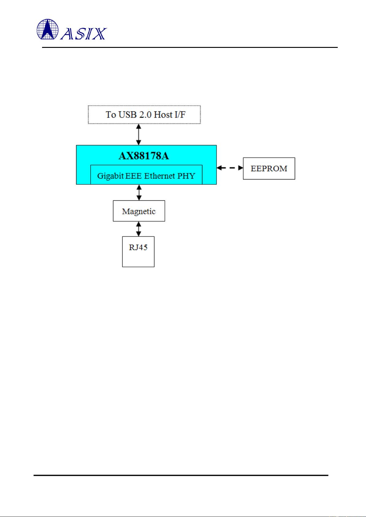
AX88178A
USB 2.0 to 10/100/1000M Gigabit Ethernet Controller
Features
Single chip USB 2.0 to 10/100/1000M Gigabit
Ethernet controller with Energy Efficient
Ethernet (EEE) base on digital signal processing
(DSP) technology with low dissipation
USB Device Controller
Integrates on-chip USB 2.0 PHY and
controller compliant to USB Spec 2.0 and 1.1
Supports USB High/Full Speed modes with
Bus-power or Self-power device auto-detect
capability
High performance packet transfer rate over
USB bus using proprietary burst transfer
mechanism (US Patent Approval)
Gigabit Ethernet Controller
Supports IEEE 802.3az (Energy Efficient
Ethernet)
IEEE 802.3, 802.3u, and 802.3ab compatible
Integrates 10/100/1000Mbps Gigabit
Ethernet MAC/PHY
Supports dynamic cable length detection and
dynamic power adjustment Green Ethernet
(Gigabit mode only)
Supports parallel detection and automatic
polarity correction
Supports crossover detection and auto-
correction
Supports IPv4/IPv6 packet Checksum
Offload Engine (COE) to reduce CPU
loading, including IPv4
IP/TCP/UDP/ICMP/IGMP & IPv6
TCP/UDP/ICMPv6 checksum check &
generation
Supports TCP Large Send Offload V1
Supports full duplex operation with IEEE
802.3x flow control and half duplex
operation with back-pressure flow control.
Supports IEEE 802.1P Layer 2 Priority
Encoding and Decoding
Supports IEEE 802.1Q VLAN tagging and
2 VLAN ID filtering; received VLAN Tag (4
bytes) can be stripped off or preserved
Supports Jumbo frame
PHY loop-back diagnostic capability
Support Wake-on-LAN Function
Supports suspend mode and remote wakeup
via link-change, Magic Packet, Microsoft
wakeup frame and external wakeup pin
Supports Bonjour wake-on-demand
Advanced Power Management Features
Supports power management offload (ARP &
NS)
Supports dynamic power management to
reduce power dissipation during idle or light
traffic
Supports AutoDetach power saving.
Soft-disconnected from USB host when
Ethernet cable is unplugged
Supports advanced link down power saving
during Ethernet cable is unplugged
Supports optional serial EEPROM (93c56/66)
for storing USB Descriptors, Node-ID, etc
Supports embedded eFuse (64-byte) to store
USB Device Descriptors, Node-ID, etc. to save
external EEPROM
Supports automatic loading of USB Device
Descriptors, Node-ID, etc. from embedded
eFuse or external EEPROM after power-on
initialization
Single 25MHz clock input from either crystal or
oscillator source
Integrates on-chip power-on reset circuit
Integrates pipelined RISC (System on a Chip,
SoC) for handling protocol and control functions
68-pin QFN 8mm x 8mm RoHS/REACH
compliant package
Operating over 0°C to 70°C temperature range
Target Applications
USB Dongle
Docking Station
USB Port Replicator
Network Printer
POS, Card Reader
UMPC, MID, Netbook
Ultrabook
Game Console
IP STB, IP TV
Embedded system
Document No: AX88178A/V1.10/05/06/13
1
AX88178A
USB 2.0 to 10/100/1000M Gigabit Ethernet Controller
Copyright © 2012-2013 ASIX Electronics Corporation. All rights reserved.
Typical System Block Diagrams
Hosted by USB to operate with internal Ethernet PHY only
Figure 1 : USB 2.0 to Gigabit LAN Adaptor
2
AX88178A
USB 2.0 to 10/100/1000M Gigabit Ethernet Controller
Copyright © 2012-2013 ASIX Electronics Corporation. All rights reserved.
DISCLAIMER
No part of this document may be reproduced or transmitted in any form or by any means, electronic or mechanical,
including photocopying and recording, for any purpose, without the express written permission of ASIX. ASIX may make
changes to the product specifications and descriptions in this document at any time, without notice.
ASIX provides this document “as is” without warranty of any kind, either expressed or implied, including without
limitation warranties of merchantability, fitness for a particular purpose, and non-infringement.
Designers must not rely on the absence or characteristics of any features or registers marked “reserved”, “undefined” or
“NC”. ASIX reserves these for future definition and shall have no responsibility whatsoever for conflicts or
incompatibilities arising from future changes to them. Always contact ASIX to get the latest document before starting a
design of ASIX products.
TRADEMARKS
ASIX, the ASIX logo are registered trademarks of ASIX Electronics Corporation. All other trademarks are the property of
their respective owners.
3
AX88178A
USB 2.0 to 10/100/1000M Gigabit Ethernet Controller
Copyright © 2012-2013 ASIX Electronics Corporation. All rights reserved.
Table of Contents
1 INTRODUCTION ....................................................................................................................................................... 6
1.1 GENERAL DESCRIPTION .......................................................................................................................................... 6
1.2 BLOCK DIAGRAM ................................................................................................................................................... 6
1.3 PINOUT DIAGRAM ................................................................................................................................................... 7
2 SIGNAL DESCRIPTION ........................................................................................................................................... 8
2.1 68-PIN PINOUT DESCRIPTION .................................................................................................................................. 8
2.2 HARDWARE SETTING FOR OPERATION MODE AND MULTI-FUNCTION PINS ......................................................... 10
3 FUNCTION DESCRIPTION ................................................................................................................................... 11
3.1 USB CORE AND INTERFACES ................................................................................................................................ 11
3.2 ENERGY EFFICIENT ETHERNET (EEE) .................................................................................................................. 11
3.3 10/100/1000M ETHERNET PHY ........................................................................................................................... 11
3.4 GMAC CORE ....................................................................................................................................................... 12
3.5 CHECKSUM OFFLOAD ENGINE (COE) ................................................................................................................... 12
3.6 MEMORY ARBITER ............................................................................................................................................... 12
3.7 USB TO ETHERNET BRIDGE .................................................................................................................................. 13
3.8 EFUSE AND CONTROL ........................................................................................................................................... 13
3.9 SEEPROM LOADER INTERFACE .......................................................................................................................... 13
3.10 GENERAL PURPOSE I/O AND LED ........................................................................................................................ 13
3.11 PLL CLOCK GENERATOR ..................................................................................................................................... 14
3.12 RESET GENERATION ............................................................................................................................................. 15
4 SERIAL EEPROM/EFUSE MEMORY MAP ........................................................................................................ 16
4.1 DETAILED DESCRIPTION ....................................................................................................................................... 18
4.1.1 Node ID (00~02h) ........................................................................................................................................ 18
4.1.2 Flag (EEPROM: 05h, eFuse:18h) ............................................................................................................... 18
4.1.3 Max. Power for Self/Bus Power (07h) ......................................................................................................... 19
4.1.4 EndPoint1 for HS/FS (EEPROM:08h, eFuse: 06h) ..................................................................................... 19
4.1.5 LED Mode (EEPROM: 42h, eFuse: 19h~1Ah) ............................................................................................ 20
4.1.6 Fixed_pattern (EEPROM: 41~3Dh, eFuse: 1F~1Ah) ................................................................................. 21
4.2 INTERNAL ROM DEFAULT SETTINGS ................................................................................................................... 22
4.2.1 Internal ROM Description ........................................................................................................................... 23
4.2.2 External EEPROM Description ................................................................................................................... 26
5 USB CONFIGURATION STRUCTURE ................................................................................................................ 27
5.1 USB CONFIGURATION .......................................................................................................................................... 27
4
AX88178A
USB 2.0 to 10/100/1000M Gigabit Ethernet Controller
Copyright © 2012-2013 ASIX Electronics Corporation. All rights reserved.
5.2 USB INTERFACE ................................................................................................................................................... 27
5.3 USB ENDPOINTS ................................................................................................................................................... 27
6 ELECTRICAL SPECIFICATIONS ........................................................................................................................ 28
6.1 DC CHARACTERISTICS ......................................................................................................................................... 28
6.1.1 Absolute Maximum Ratings ......................................................................................................................... 28
6.1.2 Recommended Operating Condition ............................................................................................................ 28
6.1.3 Leakage Current and Capacitance .............................................................................................................. 29
6.1.4 DC Characteristics of 3.3V I/O Pins ........................................................................................................... 29
6.2 THERMAL CHARACTERISTICS ............................................................................................................................... 29
6.3 POWER CONSUMPTION ......................................................................................................................................... 30
6.4 POWER-UP SEQUENCE .......................................................................................................................................... 31
6.5 AC TIMING CHARACTERISTICS ............................................................................................................................. 32
6.5.1 Clock Timing ................................................................................................................................................ 32
6.5.2 Reset Timing ................................................................................................................................................ 32
6.5.3 Serial EEPROM Timing ............................................................................................................................... 33
7 PACKAGE INFORMATION ................................................................................................................................... 34
7.1 68-PIN QFN 8X8 PACKAGE ................................................................................................................................... 34
7.2 RECOMMENDED PCB FOOTPRINT FOR 68-PIN QFN 8X8 PACKAGE ....................................................................... 35
8 ORDERING INFORMATION ................................................................................................................................. 36
9 REVISION HISTORY .............................................................................................................................................. 37
APPENDIX A. DEFAULT WAKE-ON-LAN (DWOL) READY MODE ..................................................................... 38
剩余41页未读,继续阅读
资源评论
- qq_173683112015-02-03很不错的资料,急需
pjqianqian
- 粉丝: 0
- 资源: 1
上传资源 快速赚钱
- 我的内容管理 展开
- 我的资源 快来上传第一个资源
- 我的收益 登录查看自己的收益
- 我的积分 登录查看自己的积分
- 我的C币 登录后查看C币余额
- 我的收藏
- 我的下载
- 下载帮助
安全验证
文档复制为VIP权益,开通VIP直接复制
信息提交成功