没有合适的资源?快使用搜索试试~ 我知道了~
资源推荐
资源详情
资源评论
Typical ASIC design flow .................................................................................................................2
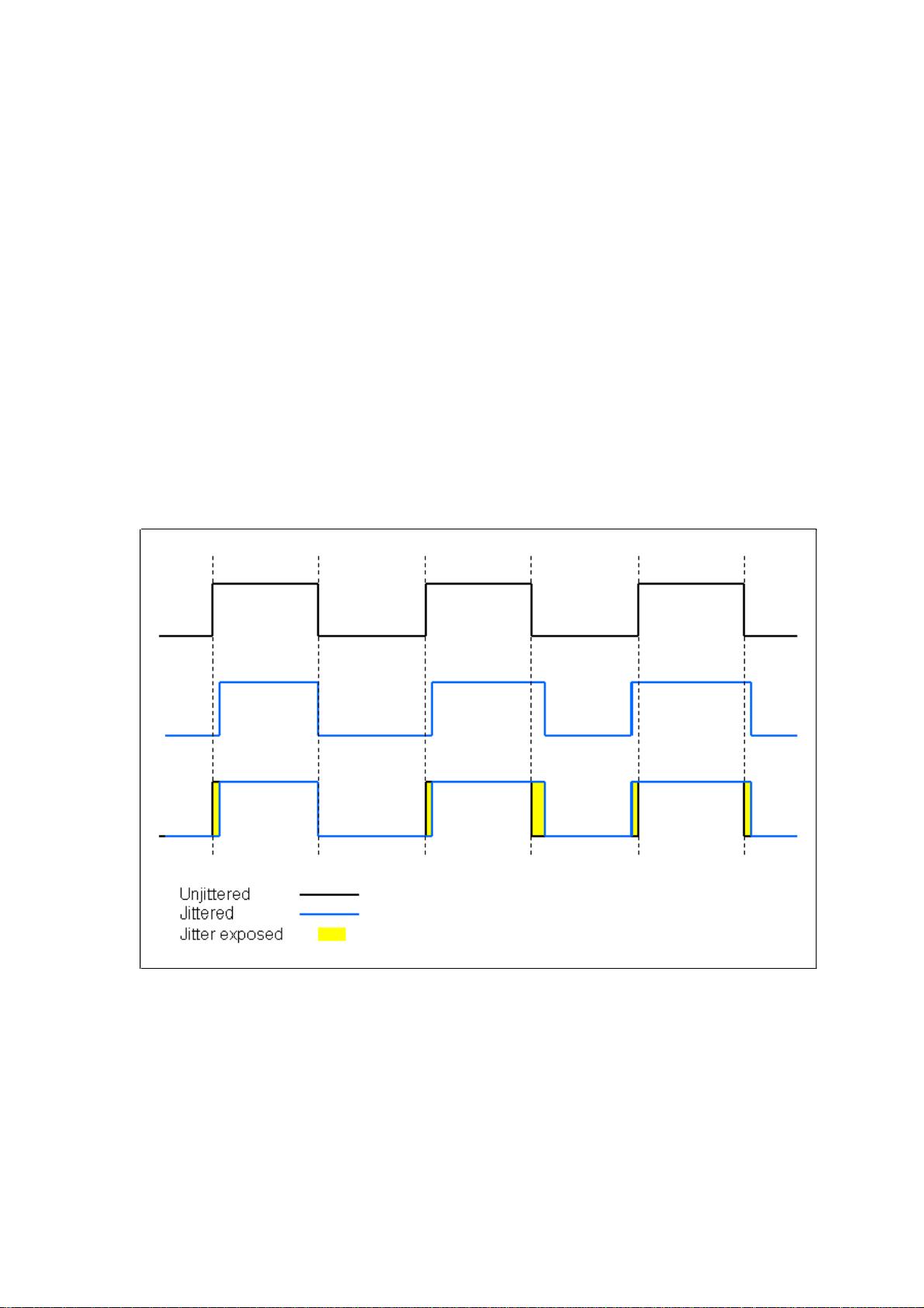
时钟抖动 (Clock Jitter) ....................................................................................................................5
信号同步的窍门...............................................................................................................................8
数字后端流程...................................................................................................................................9
DC 概论之一 setup time 与 hold time .......................................................................................11
DC 概论二之 fanout 与 skew.........................................................................................................14
DC 概论三之 setup time 与 hold time 之二................................................................................21
DC 概论四之 setup time 与 hold time 之三.................................................................................26
DC 概论五之 high fanout...............................................................................................................42
DC 概论六之 multicycle_path ......................................................................................................58
DC 概论七之 gated clock...............................................................................................................75
DC 概论之 IO 约束........................................................................................................................84
DC 优化约束 ..................................................................................................................................90
Synopsys Synthesis Constraints Template ......................................................................................92
功耗和门控时钟的的基本概念.....................................................................................................95
对 FALSE PATH 的理解 ................................................................................................................97
TimeQuest 时钟分析....................................................................................................................101
静态时序分析...............................................................................................................................105
寄生参数提取和静态时序分析...................................................................................................124
IC 设计中的时钟类型约束..........................................................................................................130
IC 设计流程及工具......................................................................................................................132
Typical ASIC design flow
Step 1: Prepare an Requirement Specification
Step 2: Create an Micro-Architecture Document.
Step 3: RTL Design & Development of IP's
Step 4: Functional verification all the IP's/Check whether the RTL is free from
Linting Errors/Analyze whether the RTL is Synthesis friendly.
Step 4a: Perform Cycle-based verification(Functional) to verify the protocol
behaviour of the RTL
Step 4b: Perform Property Checking , to verify the RTL implementation and the
specification understanding is matching.
Step 5: Prepare the Design Constraints file (clock
definitions(frequency/uncertainity/jitter),I/O delay definitions, Output pad load
definition, Design False/Multicycle-paths) to perform Synthesis, usually called as an
SDC synopsys_constraints, specific to synopsys synthesis Tool (design-compiler)
Step 6: To Perform Synthesis for the IP, the inputs to the tool are (library file(for
which synthesis needs to be targeted for, which has the functional/timing information
available for the standard-cell library and the wire-load models for the wires based on
the fanout length of the connectivity), RTL files and the Design Constraint files, So
that the Synthesis tool can perform the synthesis of the RTL files and map and
optimize to meet the design-constraints requirements. After performing synthesis, as a
part of the synthesis flow, need to build scan-chain connectivity based on the
DFT(Design for Test) requirement, the synthesis tool (Test-compiler), builds the
scan-chain.
7: Check whether the Design is meeting the requirements
(Functional/Timing/Area/Power/DFT) after synthesis.
Step 7a: Perform the Netlist-level Power Analysis, to know whether the design is
meeting the power targets.
Step 7b: Perform Gate-level Simulation with the Synthesized Netlist to check whether
the design is meeting the functional requirements.
Step 7c: Perform Formal-verification between RTL vs Synthesized Netlist to confirm
that the synthesis Tool has not altered the functionality.
Step 7d: Perform STA(Static Timing Analysis) with the SDF(Standard Delay Format)
验证
准备设计
约束文件
DC对IP综合
综合之后
检查设计
是否满足
各种要求
(功能、
时序、面
积、功耗
等)
功能验证
形式验证
静态时序分析
file and synthesized netlist file, to check whether the Design is meeting the
timing-requirements.
Step 7e: Perform Scan-Tracing , in the DFT tool, to check whether the scan-chain is
built based on the DFT requirement.
Step 8: Once the synthesis is performed the synthesized netlist file(VHDL/Verilog
format) and the SDC (constraints file) is passed as input files to the Placement and
Routing Tool to perform the back-end Actitivities.
Step 9: The next step is the Floor-planning, which means placing the IP's based on the
connectivity,placing the memories, Create the Pad-ring, placing the
Pads(Signal/power/transfer-cells(to switch voltage domains/Corner pads(proper
accessibility for Package routing), meeting the SSN requirements(Simultaneous
Switching Noise) that when the high-speed bus is switching that it doesn't create any
noise related acitivities, creating an optimised floorplan, where the design meets the
utilization targets of the chip.
Step 9a : Release the floor-planned information to the package team, to perform the
package feasibility analysis for the pad-ring .
Step 9b: To the placement tool, rows are cut, blockages are created where the tool is
prevented from placing the cells, then the physical placement of the cells is performed
based on the timing/area requirements.The power-grid is built to meet the
power-target's of the Chip .
Step 10: The next step is to perform the Routing., at first the Global routing and
Detailed routing, meeting the DRC(Design Rule Check) requirement as per the
fabrication requirement.
Step 11: After performing Routing then the routed Verilog netlist, standard-cells
LEF/DEF file is taken to the Extraction tool (to extract the parasitics(RLC) values of
the chip in the SPEF format(Standard parasitics Exchange Format), and the SPEF file
is generated.
Step 12: Check whether the Design is meeting the requirements
(Functional/Timing/Area/Power/DFT/DRC/LVS/ERC/ESD/SI/IR-Drop) after
Placement and Routing step.
Step 12a: Perform the Routed Netlist-level Power Analysis, to know whether the
design has met the power targets.
Step 12b: Perform Gate-level Simulation with the routed Netlist to check whether the
design is meeting the functional requirement .
布局布线之后
检查设计是否
满足各种要求
功能验证
Step 12c: Perform Formal-verification between RTL vs routed Netlist to confirm that
the place & route Tool has not altered the functionality.
Step 12d: Perform STA(Static Timing Analysis) with the SPEF file and routed netlist
file, to check whether the Design is meeting the timing-requirements.
Step 12e: Perform Scan-Tracing , in the DFT tool, to check whether the scan-chain is
built based on the DFT requirement, Peform the Fault-coverage with the DFT tool and
Generate the ATPG test-vectors.
Step 12f: Convert the ATPG test-vector to a tester understandable format(WGL)
Step 12g: Perform DRC(Design Rule Check) verfication called as
Physical-verification, to confirm that the design is meeting the Fabrication
requirements.
Step 12h: Perform LVS(layout vs Spice) check, a part of the verification which takes
a routed netlist converts to spice (call it SPICE-R) and convert the Synthesized
netlist(call it SPICE-S) and compare that the two are matching.
Step 12i : Perform the ERC(Electrical Rule Checking) check, to know that the design
is meeting the ERC requirement.
Step 12j: Perform the ESD Check, so that the proper back-to-back diodes are placed
and proper guarding is there in case if we have both analog and digital portions in our
Chip. We have seperate Power and Grounds for both Digital and Analog Portions, to
reduce the Substrate-noise.
Step 12k: Perform seperate STA(Static Timing Analysis) , to verify that the
Signal-integrity of our Chip. To perform this to the STA tool, the routed netlist and
SPEF file(parasitics including coupling capacitances values), are fed to the tool. This
check is important as the signal-integrity effect can cause cross-talk delay and
cross-talk noise effects, and hinder in the functionality/timing aspects of the design.
Step 12l: Perform IR Drop analysis, that the Power-grid is so robust enough to
with-stand the static and dynamic power-drops with in the design and the IR-drop is
with-in the target limits.
Step 13: Once the routed design is verified for the design constraints, then now the
next step is chip-finishing activities (like metal-slotting, placing de-coupling caps).
Step 14: Now the Chip Design is ready to go to the Fabrication unit, release files
which the fab can understand, GDS file.
等价性验证
静态时序分析
Step 15: After the GDS file is released , perform the LAPO check so that the database
released to the fab is correct.
Step 16: Perform the Package wire-bonding, which connects the chip to the Package.
Step 5: Prepare the Design Constraints file (clock definitions(frequency/uncertainity/jitter),I/O
delay definitions, Output pad load definition, Design False/Multicycle-paths) to perform Synthesis,
usually called as an SDC synopsys_constraints, specific to synopsys synthesis Tool
(design-compiler)
时钟抖动 (Clock Jitter)
通常希望一个周期性波形(特别是时钟)跨过特定门限的时间非常精确,与该理想值的偏差称
为抖动。
剩余133页未读,继续阅读
资源评论
liqi8864
- 粉丝: 0
- 资源: 6
上传资源 快速赚钱
- 我的内容管理 展开
- 我的资源 快来上传第一个资源
- 我的收益 登录查看自己的收益
- 我的积分 登录查看自己的积分
- 我的C币 登录后查看C币余额
- 我的收藏
- 我的下载
- 下载帮助
安全验证
文档复制为VIP权益,开通VIP直接复制
信息提交成功