


NFC Reader Antenna Design 4
Optimization & Debugging
Renke Bienert
Session 04: Optimization & Debugging
21 May 2014
PUBLIC
Renke Bienert
RF engineer since 1996
RFID and NFC Expert since 2001
Technical consulting for e.g.
– RFID ticketing of the FIFA world cup 2006
– the development of the Technical Guidelines for the Secure Use of RFID (BSI TR-
03126)
– standardization of contactless payment at EMVco
Chairman of the DIN working group NIA 17.8 (until 2009)
May 21, 2014 NFC Reader Antenna Design 4 / Renke Bienert
2
Member of various DIN and ISO/IEC working groups (until
2009)
Co-Author of the book “RFID - MIFARE and Contactless
Smartcards in Application“, Elektor International Media BV
2013, ISBN 978-1-907920-14-1

PUBLIC
NFC Reader Antenna Design 4:
Optimization & Debugging
What have we done last time?
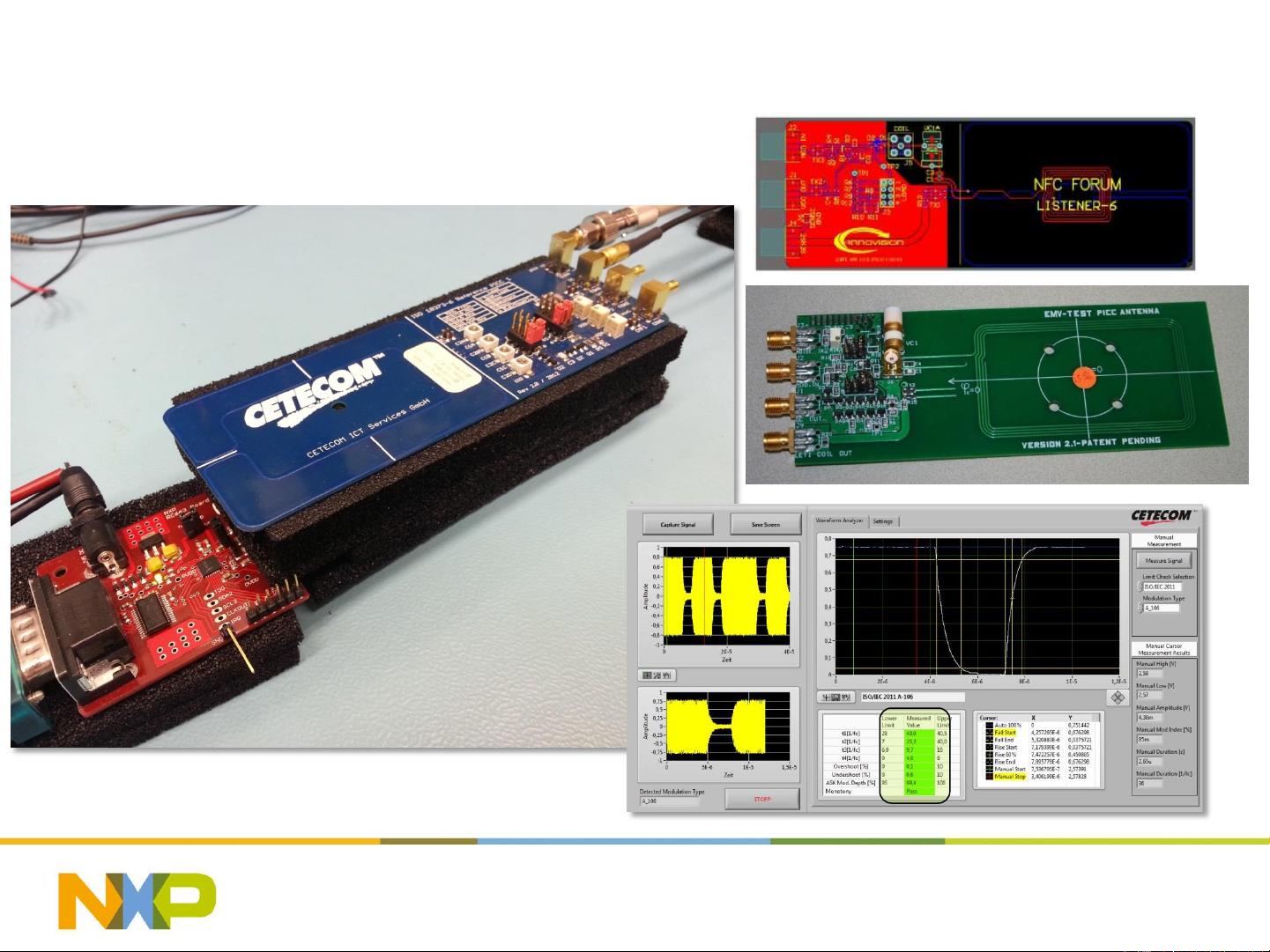
How can we guarantee proper functionality?
– Measure the current consumption (ITVDD)
– Measure field strength: ANT#5
– Measure wave shapes: ANT#5
– Measure & adjust the Rx level
How can we optimize performance?
– Use a sniffer
– Use test & debug signals
– Test receiver signals to optimize register settings
– Show “good” and “bad” signals
Q&A
May 21, 2014 NFC Reader Antenna Design 4 / Renke Bienert
3
Part of compliance tests
Example
PUBLIC
ANT#3: Metal Environment
May 21, 2014 NFC Reader Antenna Design 4 / Renke Bienert
4
0 2 6 4
d
35mm
minimum field strength
1.5 A/m
Field strength
color map
metal plate ferrite plate
|H| [A/m]

PUBLIC
The last NFC Reader Antenna Design session
Metal environment detunes the antenna.
– Can be easily compensated (retuning)
Metal environment decreases the field strength.
– Can only be compensated with ferrite (if at all).
Metal + ferrite
– Requires a new tuning (compared to no metal/ferrite),
– Has a changed field distribution,
– May achieve the same performance.
Different ferrites have different effects. Some ferrite foils
– have a better Q.
– provide a better field distribution (reader mode).
– provide a better LMA (card mode)
May 21, 2014 NFC Reader Antenna Design 4 / Renke Bienert
5


