没有合适的资源?快使用搜索试试~ 我知道了~
AN--PIC16F690--BLDC.pdf
需积分: 10 15 下载量 107 浏览量
2009-05-28
15:00:48
上传
评论
收藏 482KB PDF 举报
温馨提示
试读
18页
The article introduces application of C8051F020 in rotate speed Control of direct current and brushless motor, realization method,configuration of software and hardware. [Keywords]: MCU,direct current and brushless motor, rotate speed Control
资源推荐
资源详情
资源评论
© 2008 Microchip Technology Inc. DS01175A-page 1
AN1175
INTRODUCTION
There is a lot of interest in using Brushless DC (BLDC)
motors. Among the many advantages to a BLDC motor
over a brushed DC motor, we can enumerate the
following:
• The absence of the mechanical commutator
allows higher speeds
• Brush performance limits the transient response
in the DC motor
• With the DC motor you have to add the voltage
drop in the brushes among motor losses
• Brush restrictions on reactance voltage of the
armature constrains the length of core reducing
the speed response and increasing the inertia for
a specific torque
• The source of heating in the BLDC motor is in the
stator, while in the DC motor it is in the rotor,
therefore it is easier to dissipate heat in the BLDC
• Reduced audible and electromagnetic noise
There are many different types of brushless motors,
and the differences are:
- The number of phases in the stator
- The number of poles in the rotor
- The position of the rotor and stator relative to
each other (rotor spinning inside the stator
vs. rotor spinning outside the stator)
This application note will discuss the three-phase
motors. Two-phase motors are discussed in AN1178,
“Intelligent Fan Control” (DS01178) while one-phase
motors are a degenerated form of two-phase motors.
BACKGROUND
For a full description of three-phase brushless motors,
read the application note “Brushless DC Motor Control
Made Easy” (DS00857). AN857 is an excellent
description of brushless motors and how to drive them
with sensor feedback for commutation. With more
advanced comparator modes and some new software
techniques, this application note demonstrates an
improved sensorless commutation strategy that has a
much higher performance.
MOTOR CONTROL
BLDC motor control consists of two parts. Part 1 is
commutating the motor at the most efficient rate. Part 2
is regulating the speed of the motor within defined
parameters. The purpose of this application note is to
illustrate an elegant sensorless technique that can be
implemented on low-cost microcontrollers. All demon-
stration software will operate within an open loop with
no speed regulation.
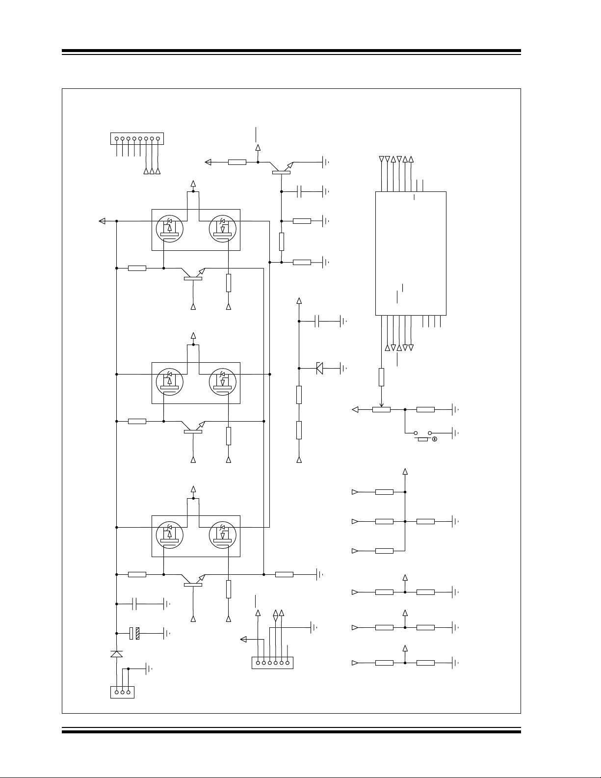
HARDWARE
The hardware for a BLDC system can be decomposed
into the following sections:
- Motor Power Drivers,
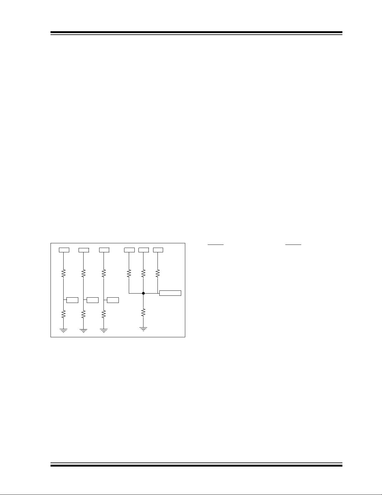
- Rotor position detection using back EMF
sensing
- Current Monitoring
- Microcontroller
- Microcontroller Power Supply
- Speed Set-point Input
Motor Power Driver
All BLDC motors require three half-bridge driver
stages. Each stage controls one phase of the motor, as
illustrated in Table 1 below:
Author: Joseph Julicher
Dieter Peter
Microchip Technology Inc.
Sensorless Brushless DC Motor Control with PIC16
AN1175
DS01175A-page 2 © 2008 Microchip Technology Inc.
FIGURE 1: MOTOR POWER DRIVER
Q6
220
VBUS
J2
Q3
TPC8405
Toshiba
U
W
V
MM8-F
1
2
3
4
5
6
7
8
3
4
R6
220
BC847B
5/6
7/8
W
Vcc
1
2
R21
47k
MCLR
Q7
BC847B
Overcurrent
Detection
R19
3k3
R20
47k
C3
100n
R7
R33
2010
16
15
14
7
6
5
8
9
V_STAR
V_V
W_L
V_W
V_L
U_L
RC0/AN4/C2IN+
RC1/AN5/C12IN1-
RC2/AN6/C12IN2-/P1D
RC3/AN7/C12IN3-/P1C
RC4/C2OUT/P1B
RC5/CCP1/P1A
RC6/AN8/SS
RC7/AN9/SDO
PIC16F690
RA0/AN0/C1IN+/ICSPDAT/ULPWU
RA1/AN1/C12IN0-/V
REF/ICSPCLK
RA2/AN2/T0CKI/INT/C1OUT
RA3/MCLR/V
PP
RA4/AN3/T1G/OSC2/CLKOUT
RA5/T1CKI/OSC1/CLKIN
RB4/AN10/SDI/SDA
RB5/AN11/RX/DT
RB6/SCK/SCL
RB7/TX/CK
U1
RA0
RA1
19
18
17
4
3
2
13
12
11
10
V
DD
C4
100n
Zener 5.1V
D2
R23
R22
220
220
VBUS
MCLR
V_U
U_H
V_H
W_H
R25
RV1
R24
SW1
R18
V
DD
25k
47k
Start/Stop
1
2
3k3
V_STAR
Speed
R17
47k
R16
47k
R15
47k
W
VU
V_W
Star-Point Reconstruction
BUS-Voltage Divider
R13
R11
R8
47k
47k
47k
10k
10k 10k
R9 R12
R14
V_U
V_V
U
V
W
V W_H
W_L
R3
220
Q5
BC847B
5/6
7/8
V_L
V_HU
Q2
TPC8405
Toshiba
1
2
4
3
R5
220
R2
220
Q1
TPC8405
Toshiba
5/6
7/8
3
4
2
1
Q4
BC847B
R10
220
R1
220
U_L
U_H
V
DD
R4
220
J3
C2
C1
D1
J1
100n
16V
47u
16V
S3A
DC 2.5mm
2
3
1
1
2
3
4
5
6
CONN-SIL6
ICD-Connector
MCLR
RA0
RA1
Optional
© 2008 Microchip Technology Inc. DS01175A-page 3
AN1175
In this sample schematic, there are three P-Channel
MOSFETS controlling the current flow from +V
CC into
each phase. There are also three N-Channel MOS-
FETS controlling the current flow from each phase into
ground. Between the N-Channel MOSFETS and
ground there is a small resistor (R7) that allows the cur-
rent through the motor to be sensed as a small voltage
proportional to the current. Three BJT transistors are
used to drive the P channel MOSFETs. The N channel
MOSFETs are driven from the PIC
®
MCU I/O pins. For
small MOSFETS and/or bipolar transistor output
stages, MOSFET drivers are not required.
Back EMF Sensing
In order to learn the current position of the rotor, it is
critical that some form of rotor position sensing is
included. In a sensored design, the rotor position sens-
ing is provided by a series of Hall effect sensors that
react to the permanent magnetics in the rotor. For sen-
sorless designs, the rotor position is provided through
knowledge of when a magnetic pole crosses the non-
driven phase. During each commutation cycle, one
phase is left undriven so it can sense the passing of a
magnet on the rotor. The following circuit is self-biased
and uses one comparator to perform the back EMF
position sensing.
FIGURE 2: BACK EMF SYSTEM
Notice that the back EMF system consists of four
elements with three of them repeating. The purpose of
these elements is to detect the zero-crossing event
even when the V
DD voltages are changing. There are
two easy ways to detect the middle of a sine wave. The
first method is to make an inverted copy and compare
them. The point where the two waves cross is the
midpoint. The second method is to make a reduced
amplitude copy and compare them. Again, the point
where the two waves cross is the midpoint. The
simplest method is the second, because it only requires
a single comparator and a few resistors. Because this
motor is a three-phase system, there are six zero-
crossings per electrical rotation, the rising edge
crossings and three falling edge crossings. When the
commutation takes place, one of the three phase inputs
is selected by writing to the CMxCON0 SFR in the
microcontroller. To save cost, there is not a hardware
filter on the comparator input, therefore, a noisy motor
can cause false zero-crossings. The solution is a
software-based majority detector. To simplify this
majority detector, the polarity bit in the CMxCON0
register is toggled with each commutation. Toggling the
comparator output polarity with each commutation
event, makes all zero-crossings look like a falling edge
on the comparator output.
Current Monitoring
Current monitoring is a nice feature for any motor con-
trol, but can be especially nice for BLDC motors. The
benefits of current monitoring are:
• High current, No zero-crossings indicate a stuck rotor
• Over-current limiting
• Torque control
Adding current monitoring is a simple task of inserting
a small sense resistor in the ground return path of the
half-bridge switching elements. An op amp may be
necessary if the sense resistor is very small.
The simplest possible over-current monitor is to simply
reset the microcontroller and restart commutation. This
method is shown in Figure 1. The current sense
resistor is used to drive the base of Q7. This transistor
will cause a Reset of the microcontroller, if external
MCLR
is enabled. If external MCLR is not enabled,
then the software can be extended to poll this input and
take corrective action if an over current condition is
detected.
SOFTWARE
The software accomplishes the following tasks:
• Start the motor
• Detect zero-crossing
• Commutate the stator
• Adjust commutation rate to match motor speed
Starting the motor
Starting the motor is the trickiest part of sensorless
drives. The simplest method to start the motor is to
simply start commutating at a slow rate and low duty
cycle. The commutating should “catch” the rotor and, at
some point, the zero-crossing detector will begin to see
crossings. Once zero-crossings can be measured, the
rotor has begun rotating in sync with the commutation,
and normal operation can begin. This method is very
simple, but there are a few problems:
• The motor can spin erratically until sync is achieved.
• The motor can sync at a harmonic of the actual speed
• It can take a long time for the motor to start-up
U
R
8
R
9
4
7
k
V_U
1
0
k
P
1
V
R
1
1
R
1
2
4
7
k
V_V
1
0
k
P
2
W
R
1
3
R
1
4
4
7
k
V_W
1
0
k
P
3
U
R
1
5
4
7
k
V
R
1
6
4
7
k
W
R
1
7
4
7
k
R
1
8
3
.
3
k
V_STAR
AN1175
DS01175A-page 4 © 2008 Microchip Technology Inc.
To resolve these drawbacks, there are other methods
that can be used to map the stalled position of the rotor
and immediately start commutating from that point.
For many motors, the simple method of a time out on
the zero-crossing forcing a commutation will result in
satisfactory performance; therefore, this is the method
for this application note.
Zero-Crossing Detector
The zero-crossing system consists of switching the
inputs to a comparator synchronously with the
commutation and monitoring the output of the
comparator. The comparator output is filtered with a
majority detector. This filter is table-driven and looks for
a transition from mostly 1’s to mostly 0’s. Once the
transition is detected, the commutation can take place.
Zero-Crossing Majority Detector
In a noiseless system, zero-crossing events can be
determined by observing when the output of a
comparator sensing the back EMF voltage transitions
from one to zero. Switching high currents at high
voltages introduces a tremendous amount of noise into
the system (see Figure 3). Determining when a zero-
crossing event occurs in such an environment requires
some sort of filtering to mitigate the noise. Filtering with
discrete components adds too much delay to be useful,
especially at high motor speeds. Discrete filters also
vary with temperature, which adds to the complexity of
delay management. A better filter is one that has a
predictable delay that does not vary with the
environment.
A majority filter is one that can be implemented in
software. Software filters have a predictable and fixed
delay that is not affected by the environment. The filter
uses a series of comparator output samples to detect a
zero-crossing event. Zero-crossing is said to have
occurred when most of the first half of the samples are
ones and most of the last half of the samples are zeros.
For a six-sample window, a zero-crossing event is
detected when two or three of the first three samples
are ones and two or three of the last three samples are
zeros. Table 1 illustrates all the possible combinations
that satisfy these criteria.
FIGURE 3: TYPICAL ZERO CROSSING
WITH PWM GENERATED
NOISE
剩余17页未读,继续阅读
资源评论
StephenGui
- 粉丝: 0
- 资源: 2
上传资源 快速赚钱
- 我的内容管理 展开
- 我的资源 快来上传第一个资源
- 我的收益 登录查看自己的收益
- 我的积分 登录查看自己的积分
- 我的C币 登录后查看C币余额
- 我的收藏
- 我的下载
- 下载帮助
安全验证
文档复制为VIP权益,开通VIP直接复制
信息提交成功