


Millipede

Millipede
www.sawapan.eu
Millipede is a Grasshopper™ component focusing on the analysis and optimization of structures.
α. Overview
At the core of this component is a library of very fast structural analysis algorithms for linear elastic systems.
The library contains its own optimization algorithms based on topology optimization but due to its speed it can
be used in combination with Galapagos for solving generic form finding problems [see included examples].
β. Stock Objects
Stock objects are shared by all analysis modules and are used in order to define materials, boundary conditions
and cross sections.
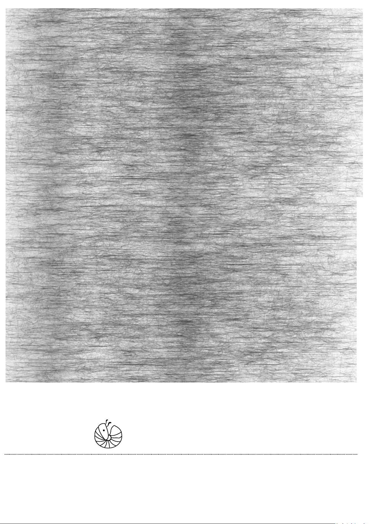
1. Material Definition
The material component allows you to select a stock material. This can be connected as an input to cross
sections and shell elements in order to assign materials.
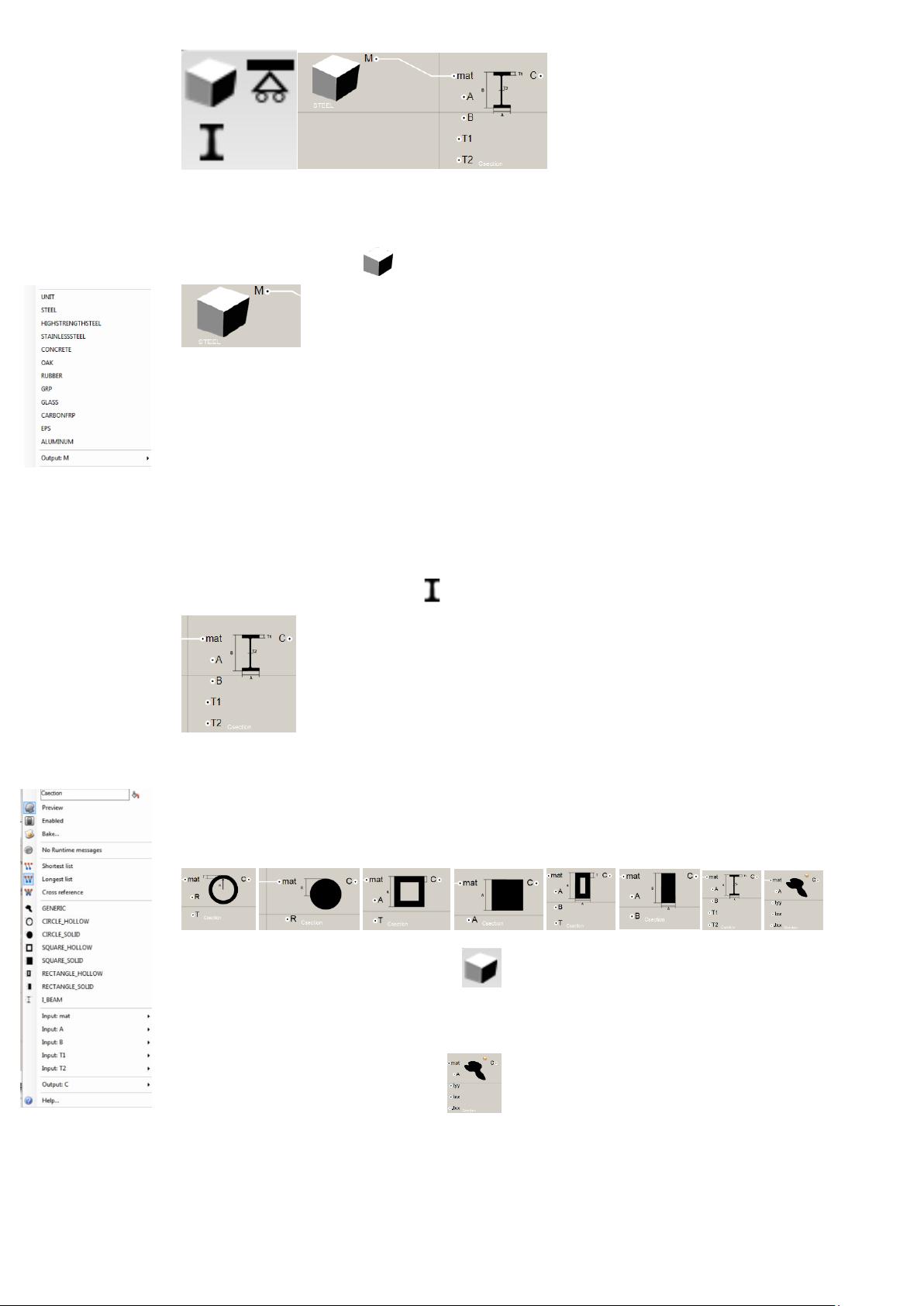
You can right click on the material component to select one of a pre-set number of materials
1. Cross Section Definition
The Cross Section component generates cross section definitions to be assigned to frame elements.
You can right click on the Cross Section component in order to choose a cross section type. Each time you
change the cross section type the input parameters of the component are changed so as to reflect the different
geometric properties of each section.
All types of cross sections receive a material definition as their first input. The rest of the parameters are
determine the dimensions according explained in each section type’s diagram icon. All dimensions are in SI
units [meters].
The special case of a generic cross section allows one to input manually the Area, Moments of Inertia
and Torsional constant [m^2 and m^4].
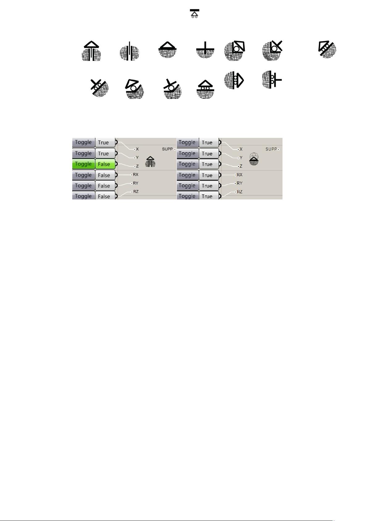
2. Boundary Condition Definition
The support component takes as inputs 6 Boolean values that determine which degrees of freedom are fixed at
a point. XYZ represent translations along the corresponding axes and RX RY RZ represent the rotations around
the corresponding axes. The component generates and integer which is a bitmask of the 6 on/off states.
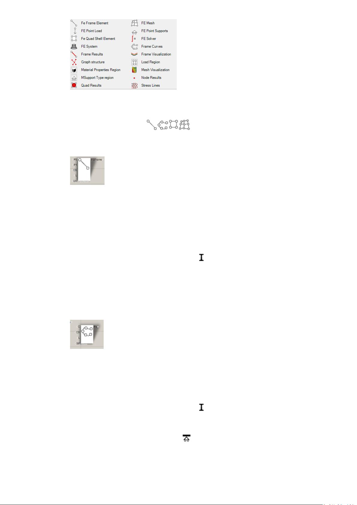
γ. Frame and Shell Element Analysis
This toolbox contains the components necessary to build analyse and optimize structures composed of frame
elements [beams, columns, trusses etc…] and shell elements.
1. Geometry constructors
These elements apply structural properties to Rhino geometry in order to be passed as inputs in the structural
system builder component.
a. Explicit Frame Element
This component creates a frame element connecting two points with a specified cross section, distributed linear
load and cross section orientation.
Inputs:
P0 [Point3d]: The start point of the frame element
P1 [Point3d]: The end point of the frame element
CS [Cross Section]: The cross section, input from component
L [Vector3d]: The distributed linear load along the element in global coordinates [N/m]
UV [Vector3d]: This is the vector that determines the orientation of the Y axis of the cross section along this
element
b. Curve
This component assigns material properties to a curve object that will be converted into a series of frame
elements during the system building phase.
Inputs:
C [Curve]: The Curve geometry
CS [Cross Section]: The cross section, input from component
L [Vector3d]: The distributed linear load along the element in global coordinates [N/m]
SP [Integer support code]: A support type to be applied to all nodes that will be generated along this curve


