没有合适的资源?快使用搜索试试~ 我知道了~
TMC260步进电机驱动IC资料
需积分: 17 11 下载量 87 浏览量
2017-11-02
21:36:41
上传
评论
收藏 1.05MB PDF 举报
温馨提示
试读
53页
TMC260 自带256细分可以实现在低速时候平滑控制,带有专利技术Coolstep可以根据电机的负载自动调节驱动芯片输出的电流,避免因为超载而丢步,也减少电机的发热量,和其他驱动芯片相比节省75%的能量
资源推荐
资源详情
资源评论
POWER DRIVER FOR STEPPER MOTORS INTEGRATED CIRCUITS
TRINAMIC Motion Control GmbH & Co. KG
Hamburg, Germany
TMC260 & TMC261 DATASHEET
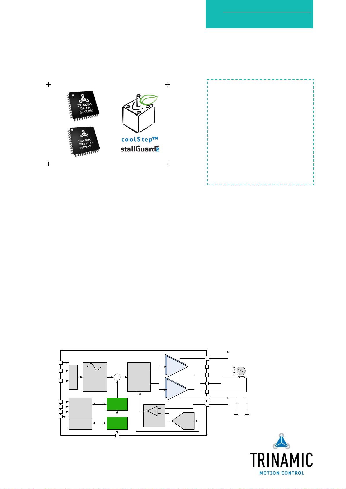
Half Bridge 2
Half Bridge 1
Half Bridge 1
Half Bridge 2
+V
M
VSA / B
2 x Current
Comparator
N
S
TMC260 / TMC261
RSA / B
Protection
& Diagnostics
Sine Table
4*256 entry
STEP
DIR
2 x DAC
SPI control,
Config & Diags
CSN
SCK
SDO
SDI
stallGuard2™
coolStep™
x
Step Multiplier
SG_TST
OA1
OA2
BRA / B
R
SENSE
R
SENSE
OB1
OB2
Chopper
VCC_IO
2 Phase
Stepper
BLOCK DIAGRAM
FEATURES AND BENEFITS
Drive Capability up to 2A motor current
Highest Voltage up to 60V DC (TMC261) or 40V DC (TMC260)
Highest Resolution up to 256 microsteps per full step
Compact Size 10x10mm QFP-44 package
Low Power Dissipation, low RDSON & synchronous
rectification
EMI-optimized programmable slope
Protection & Diagnostics overcurrent, short to GND,
overtemperature & undervoltage
stallGuard2™ high precision sensorless motor load detection
coolStep™ load dependent current control for energy savings
up to 75%
microPlyer™ microstep interpolation for increased
smoothness with coarse step inputs.
spreadCycle™ high-precision chopper for best current sine
wave form and zero crossing
APPLICATIONS
Textile, Sewing Machines
Factory Automation
Lab Automation
Liquid Handling
Medical
Office Automation
Printer and Scanner
CCTV, Security
ATM, Cash recycler
POS
Pumps and Valves
Heliostat Controller
CNC Machines
DESCRIPTION
The TMC260 and TMC261 drivers for two-
phase stepper motors offer an industry-
leading feature set, including high-
resolution microstepping, sensorless
mechanical load measurement, load-
adaptive power optimization, and low-
resonance chopper operation. Standard
SPI™ and STEP/DIR interfaces simplify
communication. Integrated power MOSFETs
handle motor currents up to 2A per coil.
Integrated protection and diagnostic
features support robust and reliable
operation. High integration, high energy
efficiency and small form factor enable
miniaturized designs with low external
component count for cost-effective and
highly competitive solutions.
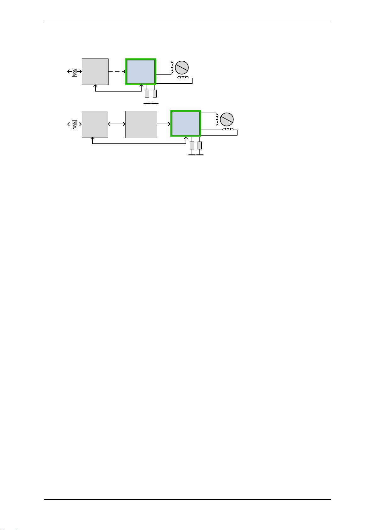
Universal, cost-effective stepper drivers for two-phase bipolar motors with state-of-the-art features.
Integrated MOSFETs for up to 2 A motor currents per coil. With Step/Dir Interface and SPI.
捷多邦,您值得信赖的PCB打样专家!
TMC260 and TMC261 DATASHEET (Rev. 2.05 / 2012-NOV-05) 2
www.trinamic.com
Layout for Evaluation
APPLICATION EXAMPLES: SMALL SIZE – BEST PERFORMANCE
The TMC260 and the TMC261 score with power density, integrated power MOSFETs, and a versatility that
covers a wide spectrum of applications and motor sizes, all while keeping costs down. Extensive support at
the chips, board, and software levels enables rapid design cycles and fast time-to-market with competitive
products. High energy efficiency from TRINAMIC’s coolStep technology delivers further cost savings in
related systems such as power supplies and cooling.
Layout for up to six stepper motors
ORDER CODES
Order code
Description
Size
TMC260-PA
coolStep™ driver with internal MOSFETs, up to 40V DC,
QFP-44 with 12x12 pins
10 x 10 mm
2
TMC261-PA
coolStep™ driver with internal MOSFETs, up to 60V DC,
QFP-44 with 12x12 pins
10 x 10 mm
2
TMC429+26x-EVAL
Chipset evaluation board for TMC429, TMC260, TMC261,
TMC262, and TMC424.
16 x 10 cm
2
TMCM-6110
FOR UP TO 6 STEPPER MOTORS
The TMCM-6110 is a compact stepper motor
controller / driver standalone board. It
supports up to 6 bipolar stepper motors with
up to 1.1A RMS coil current. The TMC260 has
been tested successfully for 2A peak (1,4A
RMS) on this module.
The TMCM-6110 features an embedded
microcontroller with USB, CAN and RS485
interfaces for communication.
All cooling requirements are satisfied by
passive convection cooling.
TMC429+TMC26X EVAL
EVALUATION & DEVELOPMENT PLATFORM
This evaluation board is a development
platform for applications based on the
TMC260, TMC261, and TMC262.
Supply voltages are 8… 40V DC (TMC260) and
8… 60V DC (TMC261 and TMC262).
The board features an embedded
microcontroller with USB and RS232 interfaces
for communication. The control software
provides a user-friendly GUI for setting control
parameters and visualizing the dynamic
responses of the motors.
Motor movements can be controlled through
the step/direction interface using inputs from
an external source or signals generated by the
TMC429 motion controller acting as a step
generator.
TMC260 and TMC261 DATASHEET (Rev. 2.05 / 2012-NOV-05) 3
www.trinamic.com
TABLE OF CONTENTS
1 PRINCIPLES OF OPERATION ............... 4
1.1 KEY CONCEPTS ............................................... 4
1.2 CONTROL INTERFACES .................................... 5
1.3 MECHANICAL LOAD SENSING ......................... 5
1.4 CURRENT CONTROL ........................................ 5
2 PIN ASSIGNMENTS ................................. 6
2.1 PACKAGE OUTLINE ......................................... 6
2.2 SIGNAL DESCRIPTIONS .................................. 6
3 INTERNAL ARCHITECTURE .................... 8
4 STALLGUARD2 LOAD MEASUREMENT 9
4.1 TUNING THE STALLGUARD2 THRESHOLD ...... 10
4.2 STALLGUARD2 MEASUREMENT FREQUENCY
AND FILTERING ............................................ 11
4.3 DETECTING A MOTOR STALL ........................ 11
4.4 LIMITS OF STALLGUARD2 OPERATION ......... 11
5 COOLSTEP LOAD-ADAPTIVE CURRENT
CONTROL 12
5.1 TUNING COOLSTEP ....................................... 14
6 SPI INTERFACE ...................................... 15
6.1 BUS SIGNALS............................................... 15
6.2 BUS TIMING ................................................ 15
6.3 BUS ARCHITECTURE ..................................... 16
6.4 REGISTER WRITE COMMANDS ...................... 17
6.5 DRIVER CONTROL REGISTER (DRVCTRL) .... 18
6.6 CHOPPER CONTROL REGISTER (CHOPCONF)
20
6.7 COOLSTEP CONTROL REGISTER (SMARTEN)21
6.8 STALLGUARD2 CONTROL REGISTER
(SGCSCONF) ............................................. 22
6.9 DRIVER CONTROL REGISTER (DRVCONF) ... 23
6.10 READ RESPONSE .......................................... 24
6.11 DEVICE INITIALIZATION ............................... 25
7 STEP/DIR INTERFACE ........................... 26
7.1 TIMING ........................................................ 26
7.2 MICROSTEP TABLE ....................................... 27
7.3 CHANGING RESOLUTION .............................. 28
7.4 MICROPLYER STEP INTERPOLATOR ............... 28
7.5 STANDSTILL CURRENT REDUCTION ................ 29
8 CURRENT SETTING ................................ 30
8.1 SENSE RESISTORS ........................................ 31
9 CHOPPER OPERATION ......................... 32
9.1 SPREADCYCLE MODE .................................... 33
9.2 CONSTANT OFF-TIME MODE ........................ 35
10 POWER MOSFET STAGE ...................... 37
10.1 BREAK-BEFORE-MAKE LOGIC ........................ 37
10.2 ENN INPUT ................................................. 37
11 DIAGNOSTICS AND PROTECTION ... 38
11.1 SHORT TO GND DETECTION ........................ 38
11.2 OPEN-LOAD DETECTION .............................. 39
11.3 OVERTEMPERATURE DETECTION ................... 39
11.4 UNDERVOLTAGE DETECTION ......................... 40
12 POWER SUPPLY SEQUENCING .......... 41
13 SYSTEM CLOCK ...................................... 42
13.1 FREQUENCY SELECTION ................................ 42
15 LAYOUT CONSIDERATIONS ............... 43
15.1 SENSE RESISTORS ........................................ 43
15.2 POWER MOSFET OUTPUTS ......................... 43
15.3 POWER FILTERING ....................................... 43
15.4 LAYOUT EXAMPLE ........................................ 44
16 ABSOLUTE MAXIMUM RATINGS ....... 45
17 ELECTRICAL CHARACTERISTICS ....... 46
17.1 OPERATIONAL RANGE .................................. 46
17.2 DC AND AC SPECIFICATIONS ...................... 46
17.3 THERMAL CHARACTERISTICS ........................ 49
18 PACKAGE MECHANICAL DATA .......... 50
18.1 DIMENSIONAL DRAWINGS ........................... 50
18.2 PACKAGE CODE ........................................... 50
19 DISCLAIMER ........................................... 51
20 ESD SENSITIVE DEVICE ...................... 51
21 TABLE OF FIGURES ............................... 52
22 REVISION HISTORY ............................. 53
23 REFERENCES ............................................ 53
TMC260 and TMC261 DATASHEET (Rev. 2.05 / 2012-NOV-05) 4
www.trinamic.com
1 Principles of Operation
µC
SPI
S/D
High-Level
Interface
N
S
0A+
0A-
0B+
TMC260
TMC261
0B-
µC
SPI
SPI
S/D
TMC429
Motion
Controller
for up to
3 Motors
High-Level
Interface
N
S
0A+
0A-
0B+
TMC260
TMC261
0B-
Figure 1.1 applications block diagram
The TMC260 and the TMC261 motor driver chips with included MOSFETs are intelligence and power
between a motion controller and the two phase stepper motor as shown in Figure 1.1. Following
power-up, an embedded microcontroller initializes the driver by sending commands over an SPI bus
to write control parameters and mode bits in the TMC260/TMC261. The microcontroller may implement
the motion-control function as shown in the upper part of the figure, or it may send commands to a
dedicated motion controller chip such as TRINAMIC’s TMC429 as shown in the lower part.
The motion controller can control the motor position by sending pulses on the STEP signal while
indicating the direction on the DIR signal. The TMC260/TMC261 has a microstep counter and sine table
to convert these signals into the coil currents which control the position of the motor. If the
microcontroller implements the motion-control function, it can write values for the coil currents
directly to the TMC260/261 over the SPI interface, in which case the STEP/DIR interface may be
disabled. This mode of operation requires software to track the motor position and reference a sine
table to calculate the coil currents.
To optimize power consumption and heat dissipation, software may also adjust coolStep and
stallGuard2 parameters in real-time, for example to implement different tradeoffs between speed and
power consumption in different modes of operation.
The motion control function is a hard real-time task which may be a burden to implement reliably
alongside other tasks on the embedded microcontroller. By offloading the motion-control function to
the TMC429, up to three motors can be operated reliably with very little demand for service from the
microcontroller. Software only needs to send target positions, and the TMC429 generates precisely
timed step pulses. Software retains full control over both the TMC260/TMC261 and TMC429 through the
SPI bus.
1.1 Key Concepts
The TMC260 and TMC261 motor drivers implement several advanced features which are exclusive to
TRINAMIC products. These features contribute toward greater precision, greater energy efficiency,
higher reliability, smoother motion, and cooler operation in many stepper motor applications.
stallGuard2™ High-precision load measurement using the back EMF on the coils
coolStep™ Load-adaptive current control which reduces energy consumption by as much as
75%
spreadCycle™ High-precision chopper algorithm available as an alternative to the traditional
constant off-time algorithm
microPlyer™ Microstep interpolator for obtaining increased smoothness of microstepping over a
STEP/DIR interface
TMC260 and TMC261 DATASHEET (Rev. 2.05 / 2012-NOV-05) 5
www.trinamic.com
In addition to these performance enhancements, TRINAMIC motor drivers also offer safeguards to
detect and protect against shorted outputs, open-circuit output, overtemperature, and undervoltage
conditions for enhancing safety and recovery from equipment malfunctions.
1.2 Control Interfaces
There are two control interfaces from the motion controller to the motor driver: the SPI serial
interface and the STEP/DIR interface. The SPI interface is used to write control information to the chip
and read back status information. This interface must be used to initialize parameters and modes
necessary to enable driving the motor. This interface may also be used for directly setting the currents
flowing through the motor coils, as an alternative to stepping the motor using the STEP and DIR
signals, so the motor can be controlled through the SPI interface alone.
The STEP/DIR interface is a traditional motor control interface available for adapting existing designs
to use TRINAMIC motor drivers. Using only the SPI interface requires slightly more CPU overhead to
look up the sine tables and send out new current values for the coils.
1.2.1 SPI Interface
The SPI interface is a bit-serial interface synchronous to a bus clock. For every bit sent from the bus
master to the bus slave, another bit is sent simultaneously from the slave to the master.
Communication between an SPI master and the TMC260 or TMC261 slave always consists of sending
one 20-bit command word and receiving one 20-bit status word.
The SPI command rate typically corresponds to the microstep rate at low velocities. At high velocities,
the rate may be limited by CPU bandwidth to 10-100 thousand commands per second, so the
application may need to change to fullstep resolution.
1.2.2 STEP/DIR Interface
The STEP/DIR interface is enabled by default. Active edges on the STEP input can be rising edges or
both rising and falling edges, as controlled by another mode bit (DEDGE). Using both edges cuts the
toggle rate of the STEP signal in half, which is useful for communication over slow interfaces such as
optically isolated interfaces.
On each active edge, the state sampled from the DIR input determines whether to step forward or
back. Each step can be a fullstep or a microstep, in which there are 2, 4, 8, 16, 32, 64, 128, or 256
microsteps per fullstep. During microstepping, a step impulse with a low state on DIR increases the
microstep counter and a high decreases the counter by an amount controlled by the microstep
resolution. An internal table translates the counter value into the sine and cosine values which
control the motor current for microstepping.
1.3 Mechanical Load Sensing
The TMC260 and TMC261 provide stallGuard2 high-resolution load measurement for determining the
mechanical load on the motor by measuring the back EMF. In addition to detecting when a motor
stalls, this feature can be used for homing to a mechanical stop without a limit switch or proximity
detector. The coolStep power-saving mechanism uses stallGuard2 to reduce the motor current to the
minimum motor current required to meet the actual load placed on the motor.
1.4 Current Control
Current into the motor coils is controlled using a cycle-by-cycle chopper mode. Two chopper modes
are available: a traditional constant off-time mode and the new spreadCycle mode. spreadCycle mode
offers smoother operation and greater power efficiency over a wide range of speed and load.
剩余52页未读,继续阅读
资源评论
flody1993
- 粉丝: 1
- 资源: 2
上传资源 快速赚钱
- 我的内容管理 展开
- 我的资源 快来上传第一个资源
- 我的收益 登录查看自己的收益
- 我的积分 登录查看自己的积分
- 我的C币 登录后查看C币余额
- 我的收藏
- 我的下载
- 下载帮助
安全验证
文档复制为VIP权益,开通VIP直接复制
信息提交成功