


Standard
Microsystems
SD Memory Card Sp
ecifications
PHYSICAL LAYER SPECIFICATION
Part 1
March 2000
SD Group
Matsushita Electric Industrial Co., Ltd. (MEI)
SanDisk Corporation
Toshiba Corporation
Version 1.0
CONFIDENTIAL

Standard
Microsystems
DO NOT COPY (c)2000 by SD Group (MEI,SanDisk,Toshiba)
2 CONFIDENTIAL
Date: March 2000
SD-Memory Card Specifications / Part 1. Physical Layer Specification; Version 1.0
Revision History
Copyright 2000 SD Group (MEI, Toshiba, SanDisk)
Date Version Changes compared to previous issue
March 22th, 2000 1.0 Base version
Conditions for publication:
-
Publisher and Copyright Holder
:
SD Group (MEI, SanDisk, Toshiba)
- Confidentiality
:
This document shall be treated as confidential under the Non Disclosure Agreement
which has been signed by the obtainer.
Reproduction in whole or in part is prohibited without prior written permission of SD Group.
- Exemption
:
Non will be liable for any damages from use of this document.

Standard
Microsystems
DO NOT COPY (c)2000 by SD Group (MEI,SanDisk,Toshiba)
3 CONFIDENTIAL
Date: February 2000
SD-Memory Card Specifications / Part 1. Physical Layer Specification; Version 1.0
1 General description - 6
2 System features - 8
3 SD Memory Card System Concept - 9
3.1 Bus Topology - 9
3.1.1 SD bus - 10
3.1.2 SPI bus - 11
3.2 Bus Protocol - 12
3.2.1 SD bus - 12
3.2.2 SPI Bus - 15
3.3 SD Memory Card - Pins and Registers - 17
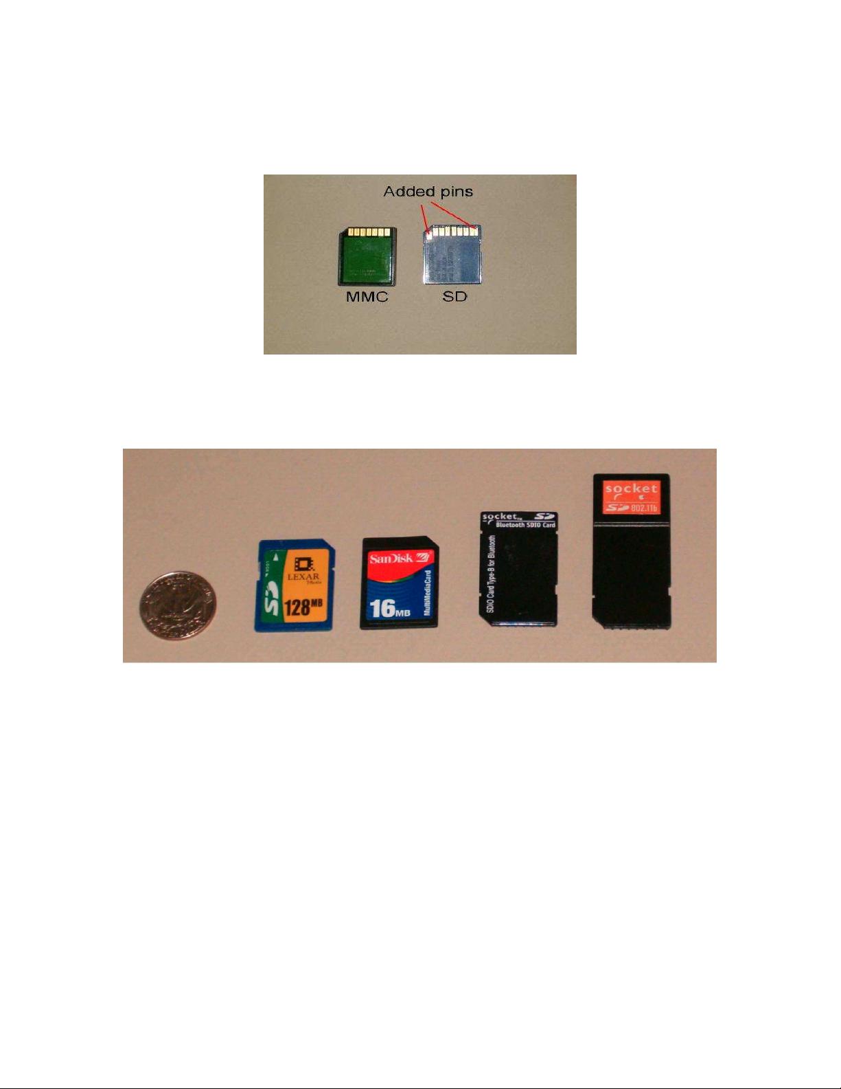
3.4 Compatibility to MultiMediaCard - 19
4 SD Memory Card Functional Description - 22
4.1 General - 22
4.2 Card Identification Mode - 23
4.2.1 Card Reset - 23
4.2.2 Operating Voltage Range Validation - 23
4.2.3 Card Identification Process - 25
4.3 Data Transfer Mode - 25
4.3.1 Wide Bus Selection/Deselection - 27
4.3.2 Data Read - 28
4.3.3 Data Write - 28
4.3.4 Erase - 29
4.3.5 Write Protect Management - 30
4.3.6 Card Lock/Unlock Operation (Optional) - 31
4.3.7 Copyright Protection - 33
4.3.8 Application specific commands - 34
4.4 Clock Control - 35
4.5 Cyclic redundancy codes (CRC) - 35
4.6 Error Conditions - 37
4.6.1 CRC and Illegal Command - 37
4.6.2 Read, Write and Erase Time-out Conditions - 37
4.7 Commands - 38
4.7.1 Command Types - 38
4.7.2 Command Format - 38
4.7.3 Command Classes (Redefined for SD Memory Card) - 39
4.7.4 Detailed Command Description - 40
4.8 Card State Transition Table - 45
4.9 Responses - 46
4.10 SD Memory Card Status - 48
4.10.1 Card Status - 48
4.10.2 SD Status - 52
4.11 Memory Array Partitioning - 52
Standard
Microsystems
DO NOT COPY (c)2000 by SD Group (MEI,SanDisk,Toshiba)
4 CONFIDENTIAL
Date: February 2000
SD-Memory Card Specifications / Part 1. Physical Layer Specification; Version 1.0
4.12 Timings - 53
4.12.1 Command and Response - 54
4.12.2 Data Read - 55
4.12.3 Data Write - 56
4.12.4 Timing Values - 59
5 Card Registers - 60
5.1 OCR Register - 60
5.2 CID Register - 61
5.3 CSD Register - 62
5.4 RCA Register - 71
5.5 DSR Register (Optional) - 71
5.6 SCR Register - 71
6 SD Memory Card Hardware Interface - 73
6.1 Hot insertion and removal - 73
6.2 Card Detection (Insertion/Removal) - 74
6.3 Power protection (Insertion/Removal) - 74
6.4 Power up - 75
6.5 Programmable card output driver (Optional) - 77
6.6 Bus operating conditions - 79
6.7 Bus signal levels - 80
6.8 Bus timing - 81
6.9 Low Voltage (1.8v) SD Memory Cards (Preliminary) - 82
7 SPI Mode - 84
7.1 Introduction - 84
7.2 SPI Bus Protocol - 84
7.2.1 Mode Selection - 84
7.2.2 Bus Transfer Protection - 85
7.2.3 Data Read - 85
7.2.4 Data Write - 86
7.2.5 Erase & Write Protect Management - 88
7.2.6 Read CID/CSD Registers - 88
7.2.7 Reset Sequence - 88
7.2.8 Error Conditions - 88
7.2.9 Memory Array Partitioning - 89
7.2.10 Card Lock/unlock - 89
7.2.11 Application Specific commands - 89
7.2.12 Copyright Protection commands - 89
7.3 SPI Mode Transaction Packets - 89
7.3.1 Command Tokens - 89
7.3.2 Responses - 94
7.3.3 Data Tokens - 96
7.3.4 Data Error Token - 97
7.3.5 Clearing Status Bits - 97

Standard
Microsystems
DO NOT COPY (c)2000 by SD Group (MEI,SanDisk,Toshiba)
5 CONFIDENTIAL
Date: February 2000
SD-Memory Card Specifications / Part 1. Physical Layer Specification; Version 1.0
7.4 Card Registers - 99
7.5 SPI Bus Timing Diagrams - 99
7.5.1 Command / Response - 100
7.5.2 Data read - 100
7.5.3 Data write - 101
7.5.4 Timing Values - 102
7.6 SPI Electrical Interface - 102
7.7 SPI Bus Operating Conditions - 102
7.8 Bus Timing - 103
8 SD Memory Card mechanical specification - 104
8.1 Card package - 104
8.1.1 External signal contacts (ESC) - 104
8.1.2 Design and format - 105
8.1.3 Reliability and durability - 105
8.1.4 Electrical Static Discharge (ESD) Requirements (Target spec) - 106
8.1.5 Quality assurance - 107
8.2 Mechanical form factor - 107
8.3 System: card and connector - 110
8.3.1 Card hot insertion - 110
8.3.2 Inverse insertion - 110
8.4 Thin (1.4mm) SD Memory Card (Preliminary) - 111
9 Appendix - 112
9.1 Power Supply Decoupling - 112
9.2 Connector - 112
9.2.1 General - 112
9.2.2 Card Insertion and Removal - 113
9.2.3 Characteristics - 114
10 Abbreviations and terms - 117


- 1
- 2
- 3
前往页