没有合适的资源?快使用搜索试试~ 我知道了~
欧洲流行的总线通讯方式
1星 需积分: 9 29 下载量 23 浏览量
2009-02-11
14:13:35
上传
评论
收藏 137KB PDF 举报
温馨提示
试读
14页
TSS721是TI公司生产的仪表总线 (Meter-Bus)终端收发芯片 ,可用于Meter-Bus与终端仪表中微处理器之间的连接。文章介绍了仪表总线的工作原理和TSS721的性能结构及工作方式 ,最后给出了TSS721的总线连接方法以及实际应用电路。
资源推荐
资源详情
资源评论
TSS721A
METER-BUS TRANSCEIVER
SLAS 222 - April 1999
1
ÿþýüûúùøý÷ö üõùõö ôóòñðïîíôñóö ôìö ëêððéóíö îìö ñòö èêçæôëîíôñóö åîíéä
ÿðñåêëíìöëñóòôðïöíñöìèéëôòôëîíôñóìöèéðöíéöíéðïìöñòöùéîìö øóìíðêïéóíì
ìíîóåîðåöîððîóí äöÿðñåêëíôñóöèðñëéììôó öåñéìöóñíöóéëéììîðôæ öôóëæêåé
íéìíôó öñòöîææöèîðîïéíéðìä
Copyright © 1999, Texas Instruments Incorporated
• Meter-Bus Transceiver
(for Slave) meets standard EN1434-3
• Receiver logic with dynamic level recognition
• Adjustable constant current sink via resistor
• Polarity independent
• Power fail function
• Module supply voltage switch
• 3.3 V constant voltage source
• Remote powering
• Up to 9600 baud in half duplex
for UART protocol
• Slave Power Support
- supply from Meter-Bus via output VDD
or from back up battery
- supply from battery – Meter-Bus active
for data transmission only
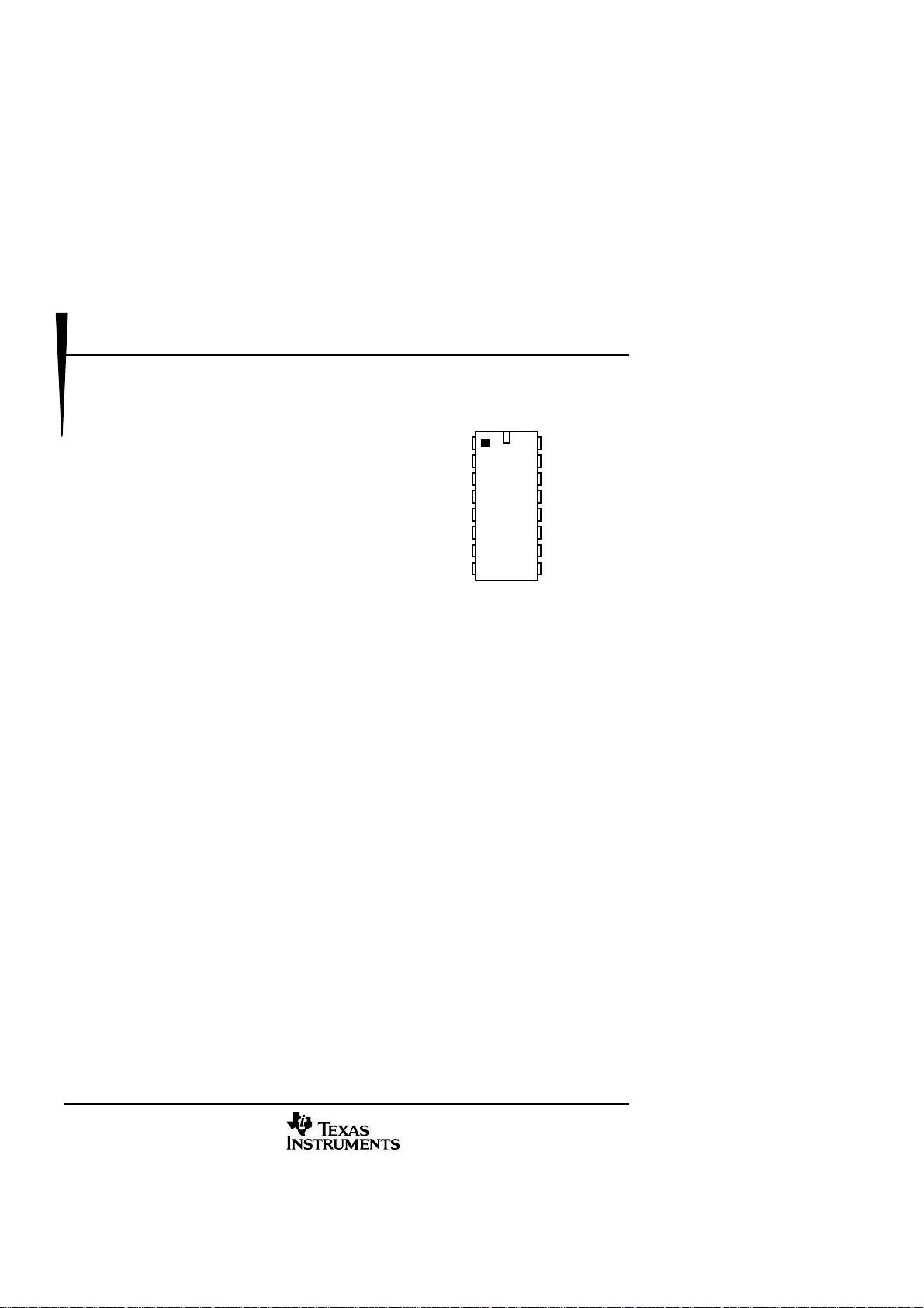
D PACKAGE
(TOP VIEW)
BUSL2
STC
VB
RIDD
PF
SC
TXI
TX
BUSL1
GND
RIS
RXI
RX
VDD
VS
BAT
description
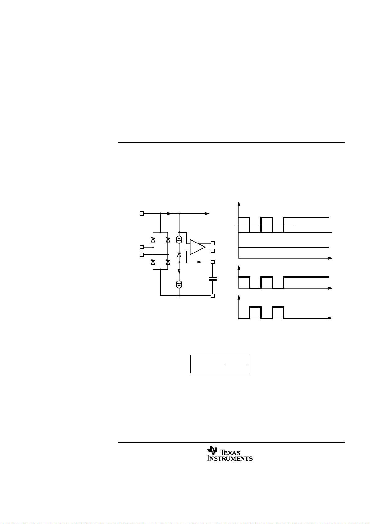
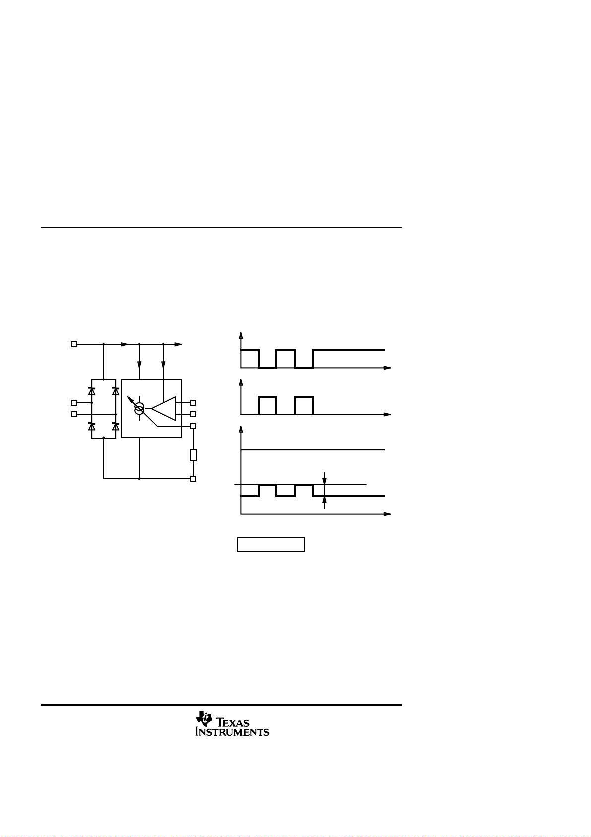
TSS721A is a single chip transceiver developed for Meter-Bus standard (EN1434-3) applications.
The TSS721A interface circuit adjusts the different potentials between a slave system and the Meter-
Bus master. The connection to the Bus is polarity independent and supports full galvanic slave
isolation with opto-couplers.
The circuit is supplied by the master via the bus. Therefore this circuit offers no additional load for the
slave battery. A power-fail function is integrated.
The receiver has dynamic level recognition, and the transmitter a programmable current sink.
A 3.3-V voltage regulator, with power reserve for a delayed switch off at bus fault, is integrated.
TSS721A
METER-BUS TRANSCEIVER
SLAS 222 - April 1999
2
function (the functional description refers to typical values)
Data Transmission Master to Slave
The mark level on the bus lines V
BUS = MARK is defined by the difference of BUSL1 and BUSL2
at the slave. It is dependent on the distance of Master to Slave, which affects the voltage drop on
the wire. To make the receiver independent, a dynamic reference level on the SC pin is used for
the voltage comparator TC3 (refer to figure 1).
BR
VB
BUSL1
GND
BUSL2
TC3
TX
TXI
SC
I SCcharge
I SCdischarge
VT
BUS
I = constant
SPACE
MARK
V = 20.8 .. 42 V
BUS
V
BUS
I
TX
V
TXI
V
V
C
SC
to IC
BUSI
MARK=V -10V
BUSL1-BUSL2C=30pFtyp.
at: VB = 25 V; f = 1MHz
meas
Figure 1
A capacitor C
SC at pin SC is charged by a current I
SCcharge
and is discharged with a current
I
SCdischarge
where:
This ratio is necessary to run any kind of UART protocol independent of the data contents.
(e. g. if an 11-Bit UART protocol is transmitted with all data bits at '0' and only the stop bit at '1').
There must be sufficient time to recharge the capacitor C
SC. The input level detector TC3 detects
voltage modulations from the master, V
BUS = SPACE/MARK conditions and switches the inverted
output TXI and the non-inverted output TX.
(typ.)
SCcharge
eSCdischarg
40
I
I
=
TSS721A
METER-BUS TRANSCEIVER
SLAS 222 - April 1999
3
Data Transmission Slave to Master
The device uses current modulation to transmit information from Slave to the Master while the
bus voltage remains constant. The current source CS3 modulates the bus current and the master
detects the modulation. The constant current source CS3 is controlled by the inverted input RXI
or the non-inverted input RX. The current source CS3 can be programmed by an external resistor
R
RIS. The modulation supply current IMS flows in addition to the current source CS3 during the
modulation time.
BR
VB
BUSL1
GND
BUSL2
ICS3
RISR
RIS
CS3
TC4
RX
RXI
IMS
BUS
V
MCI
= constant
SPACEI
MARKI
BUSV
BUSI
RX
V RXI
V
BUSI
to IC
Figure 2
Since the TSS721A is configured for half-duplex only, the current modulation from RX or RXI is
repeated concurrently as ECHO on the outputs TX and TXI. If the Slave, as well as the Master, is
trying to send information via the lines, the added signals appear on the outputs TX and TXI
which indicate the data collision to the slave (refer to figure 6).
The bus topology requires a constant current consumption by each connected slave.
CS3MSMC
III
+=
剩余13页未读,继续阅读
资源评论
- lfah0012012-11-05这是坑人的吧,拿个英文说明书,随便发过来,就要10分,一点用都没有,强烈要求赔钱。
chqlgm
- 粉丝: 1
- 资源: 2
上传资源 快速赚钱
- 我的内容管理 展开
- 我的资源 快来上传第一个资源
- 我的收益 登录查看自己的收益
- 我的积分 登录查看自己的积分
- 我的C币 登录后查看C币余额
- 我的收藏
- 我的下载
- 下载帮助
安全验证
文档复制为VIP权益,开通VIP直接复制
信息提交成功