没有合适的资源?快使用搜索试试~ 我知道了~
资源推荐
资源详情
资源评论
CHAPTER 1
INTRODUCTION
GEORGE B. COLLINS
A magnetron is a diode, usually cylindrical, with a magnetic field
parallel to its axis. Inmodern usage, ho~vever, theword implies a diode
that, with the aid of a magnetic field, produces short electromagnetic
waves, and it is with this meaning that the term is used in this volume.
Those magnetrons which produce radiation within the wavelength range
1 to 30 cm are here defined as microwave magnetrons. This class of
tubes is sometimes called cavity magnetrons from the fact that, in the
usual design, the resonant circuit is a number of closely coupled cavities
contained within the evacuated portion of the tube.
101. Early Types of Magnetrons.—k’f icrowave magnetrons and the
theory of their operation have their origin in contributions made by a
great many investigators extending back at least to 1921. A review of
this development will be given here ith the purpose of pointing out the
significant steps that have led to the present highly efficient sources of
microwaves. Editorial policy precludes the assignment of credit for
origination of ideas or inventions, and this question will be purposely
avoided as far as possible.
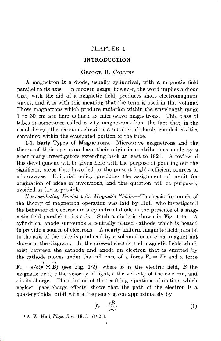
Nonoscillating Diodes with Magnetic Fields .—The basis for much of
the theory of magnetron operation was laid by Hulll who investigated
the behavior of electrons in a cylindrical diode in the presence of a mag-
netic field parallel to its axis. Such a diode is shown in Fig. 1.la. A
cylindrical anode surrounds a centrally placed cathode which is heated
to provide a source of electrons.
A nearly uniform magnetic field parallel
to the axis of the tube is produced by a solenoid or external magnet not
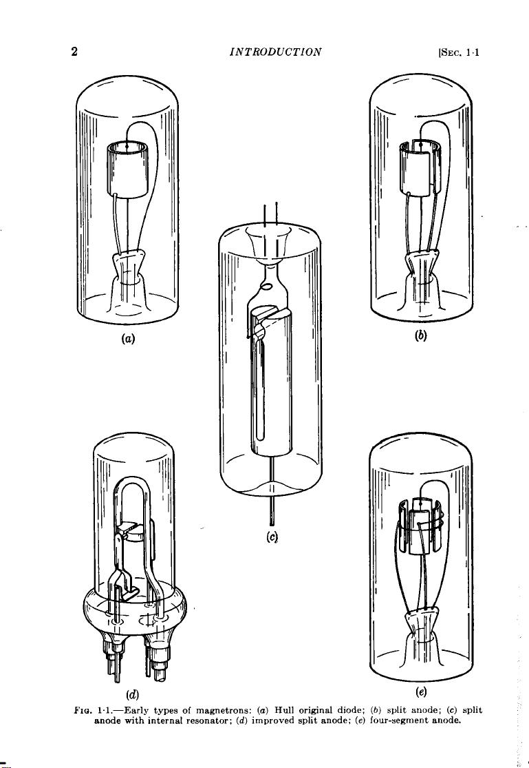
shown in the diagram. In the crossed electric and magnetic fields which
exist between the cathode and anode an electron that is emitted by
the cath;de moves under the influence of a force Fe =
Ee and a force
F~ = e/c(; X ~) (see Fig. 1.2), where
E is the electric field, B the
magnetic field, c the velocity of light, v the velocity of the electron, and
e is its charge. The solution of the resulting equations of motion, which
neglect space-charge effects, shows that the path of the electron is a
quasi-cycloidal orbit with a frequency given approximately
by
(1)
1A. W. Hull,Phgs. Re~.,18, 31 (1921).
1
(a)
INTRODUCTION
(c)
[SEC. 1]
n
(b)
FIWI.I.—Earlytypesof magnetrons:
(a) Hull originaldiode; (b)
splitanode; (c) split
anodewithinternalresonator;(d)improvedsplitanode;(e)four-segmentanode.
9CC.11]
EARLY TYPES OF MAGNETRONS 3
When this orbit touches the anode, a condition of cutoff is said to
exist, and Eq. (2) holds
$=a[l-kYY
(2)
where
V is the potential difference between the anode and the cathode
and r. and
r, are their radii. The relation
is an important one from the standpoint
of magnetron operation. It implies that
for
V/B2 less than the right side of Eq.
(2), no current flows and, as
V/B’ is
increaeed through the cutofi condition, a
rapid increase in current takes place. For
obscure reasons the reduction of current at
cutoff, which is observed experimentally, is
not so abrupt as the theory outlined above
would indicate.
Cyclotron Frequenqi Oscillations.-The
type of diode shown in Fig. 10la can be made
to oscillate at very high frequencies if the
FIG. 1.2.—Forces on an
electronmovingina diodewith
a magneticfieldparallelto its
axis.
cathode and anode are made part of a resonant circuit with reasonably
high impedance and low losses. Conditions for oscillation are that V/B’
must be adjusted close to the cutoff condition given by Eq. (2) and that
the frequency of the resonant current be close to the transit frequency of
+
FIG.1.3.—Trajectoriesofelectrons:
(1)phasewithrespectto ther-ffieldis
unfavorablefor the supportof oscil-
lations;(2)favorable.
the electrons. An explanation of these
oscillations is given in terms of Fig. 1“3.
The dashed circle represents the path of
an electron in the interaction space and
modifies the trajectories of such an elec-
tron. Curve (1) represents the trajec-
tory of an ele~tron emitted at an instant
when the r-f field is in the same direc-
tion as the d-c field. Thus the effective
V acting on the electron is increased,
and from Eq. (2) it is seen that this
increases the cutoff radius with the
result that the electron strikes the
anode.
Curve (2) is for an electron emitted one-half period later when the
r-f fields are opposed to the d-c field.
The electron now misses the anode
and returns toward the cathode. Since the frequency of rotation as
given by (1) is made close to the r-f frequency, electron (1) will return
toward the cathode also retarded by the r-f field. This electron thus
4
INTRODUCTIO>V [SEC. 1.1
contributes energy to the r-f oscillation, and the process will continue as
long as the phase relationships with the r-f field persist or until the
electron is removed by some process.
As these phase relationships
cannot be maintained indefinitely, provisions are usually made for remov-
ing the electrons before they fall out of phase. One method is to tilt
the magnetic field slightly ]vith respect to the axis of the tube. This
causes the electrons to spiral out of the end of the anode before too many
revolutions occur.
A characteristic of this type of magnetron, which is important to
the operation of many magnetrons, is the quick removal from the r-f
field of the electrons whose phase is unfavorable to the support of oscilla-
tions and the retention in the r-f field of the favorable ones.
Split-anode magnetrons such as shown in Fig. 1lb will also oscillate
when the frequency of the resonant circuit (now connected to the two
segments) is close to the transit frequency of the electrons and the anode
voltage adjusted close to cutoff conditions.
h’o satisfactory analysis
has been made that gives the trajectory of the electrons in this case, but
it is probable that the unfavorable and favorable electrons are segregated
by processes similar to that illustrated in Fig. 1.3.
h’o large number of cyclotron-type magnetrons have been made,
but they have been used effectively as experimental sources of radio
frequency.’23 At 50-cm wavelength output powers of 100 watts have
been obtained; at 10-cm wavelength about 1 watt; and detectable
radiation has been produced at 0.6 cm. The efficiency of the split-
anode tubes is around 10 per cent for moderately long wavelengths as
compared with 1 per cent for the diode variety.
The shortcomings of this class of magnetron are low efficiency, low
power, and generally erratic behavior, but extremely high frequencies
can be generated by these oscillators.
Negative Resistance or Habann Type.—If the magnetic field of a split-
anode magnetron is greatly increased over what is required for the
cyclotron-type oscillations, a new type can occur which has been called
negative-resistance or Habann-type oscillations.
The frequency is
determined almost wholly by the resonant circuit, and the magnetic
field is not critical as is the case with cyclotron oscillations. These
oscillators have been investigated by Kilgore4 who observed in a mag-
netron containing gas at low pressure, luminous paths corresponding to
electron trajectories of the form shown in Fig. 1.4.
The form of the r-f field is shown, and this combined with the d-c
1A. Zarek,Cos.Pro. Pest Math. a FTYS.JPrague,53, 578 (1924).
2H. Yagi, l%oc. IRE, 16, 715 (1926).
3C. E. Cleetonand N. H. Williams,
Phys. Ren., 60, 1091(1936).
4G. R. Kilgore,
Proc. IRE, 24, 1140(1!)36).
SEC.1.1]
EARLY TYPES OF MAGNETRONS 5
field and the high magnetic field causes the electrons to spiral out to
the anode segment that is at the lowest (most negative) potential.
The magnetron thus has the characteristics of a negative resistance neces-
sary to produce oscillations. It is observed that the efficiency of this
type of oscillation is enhanced if the electron moves out to the anode
making tenor more spirals. The frequency of thespiraling isdekmnined
by Eq. (l), and thus magnetic field strengths are needed that are ten
times those required to produce the same frequency by cyclotron-type
oscillations.
Providhg sufficiently high magnetic fields to satisfy this
requirement for very high frequencies is one of the principal objections
to this type of oscillation asa practi-
cal source of microwaves.
+150
An important modification in
the design of split-anode magne-
trons was made when the resonant
circuit was placed entirely within
the vacuum system. This step
was the result of efforts to increase , I ,
both the frequency and power out-
put. Figure 1.lc shows such a
design. This type of tube has pro-
duced power outputs of 100 to 400
watts at 50 cm and 80 watts at 20
cm.
Traveling-wave Oscillations.— +50
Electronpath
This third type of oscillation also
FIG.1.4.—Trajectoriesof anelectronin
occurs in split-anode magnetrons
a split-anodemagnetronwhenused as a
Habann-typeoscillator.
and is related to the negative resist-
ance type. The two differ only in the ratio of the angular frequency of the
traveling wave to the cyclotron frequency. In the negative-resistance
magnetron the magnetic field is so high that on the cyclotron time scale
the traveling wave remains nearly stationary. There is no sharp dividing
line between the two. For the same frequencies the magnetic field
required is much lower than that needed to produce negative-resistance
oscillations; and although the magnetic field may be close to the value
necessary to produce cyclotron-type oscillation, its value is not critical
and the anode potential is lower, so that oscillations occur below cutoff
conditions.
Traveling-wave oscillations have also been observed’ in four-segment
and even eight-segment magnetrons.
Figure 1.ld illustrates a four-
segment magnetron and shows in particular the manner in which the
alternate segments are connected together within the vacuum envelope.
1K. Posthumus,Wireless
Eng., 12, 126(1935).
剩余805页未读,继续阅读
资源评论
- quick20152017-11-11很值得一看
和谐社区
- 粉丝: 9
- 资源: 16
上传资源 快速赚钱
- 我的内容管理 展开
- 我的资源 快来上传第一个资源
- 我的收益 登录查看自己的收益
- 我的积分 登录查看自己的积分
- 我的C币 登录后查看C币余额
- 我的收藏
- 我的下载
- 下载帮助
安全验证
文档复制为VIP权益,开通VIP直接复制
信息提交成功