没有合适的资源?快使用搜索试试~ 我知道了~
温馨提示
试读
24页
This article will explain how to build ZRobot hardware project by Vivado Design Suite, including tutorials about adding user-defined IP, constructing your embedded system, synthesizing and generating bitstreams. At last we will export the project into SDK and testify.
资源推荐
资源详情
资源评论
Building ZRobot Hardware Project by
Vivado
Introduction
This article will explain how to build ZRobot hardware project by Vivado Design Suite, including tutorials
about adding user-defined IP, constructing your embedded system, synthesizing and generating
bitstreams. At last we will export the project into SDK and testify.
Goals and Perspectives
Through this article, you will learn to:
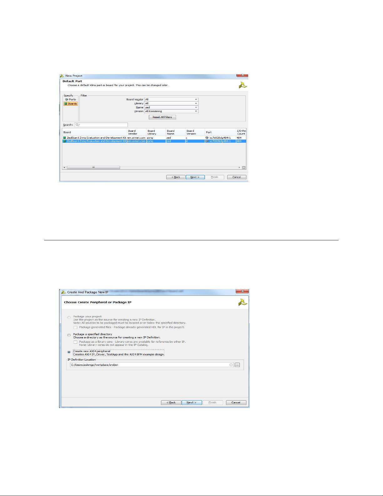
create a zedboard template in Vivado
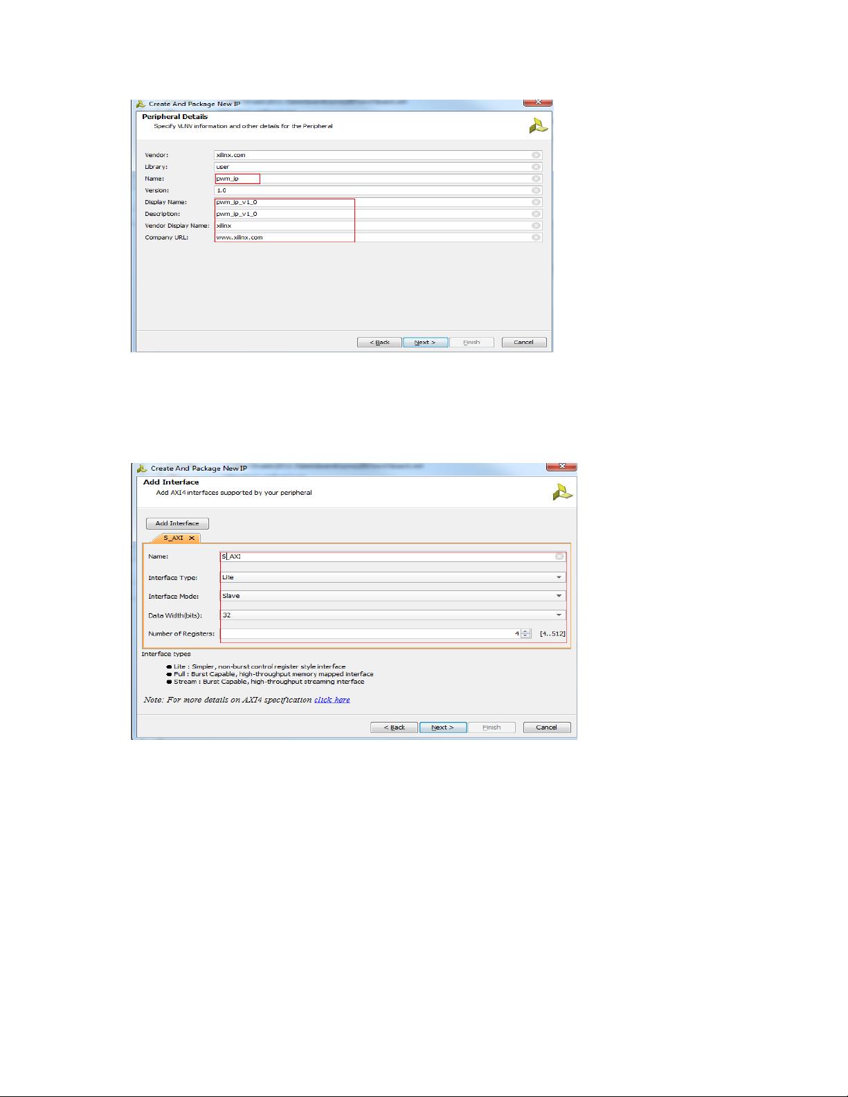
define your own IP cores
create your own bd
synthesize, constrain and generate a bitstream of your design
import your project into SDK for testing
Software and Hardware Environment
Vivado2013.3 Zrobot hardware materials SDK2013.2
Scheme
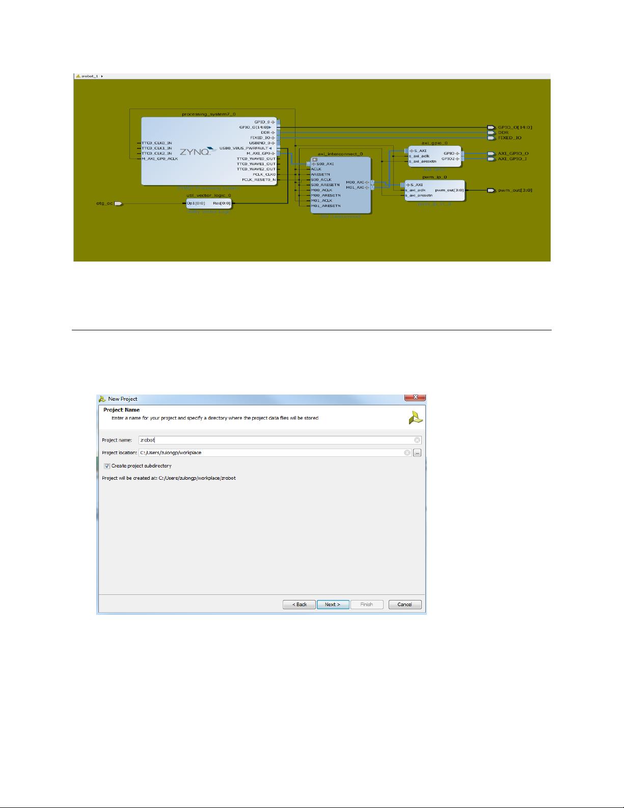
This article is based on ZRobot smart car. It implements a PWM module to control leds on zedboard as
an instance for demonstrating building your own embedded system in Vivado. The whole system
diagram is shown in Figure 1.
Figure 1. whole design
Create a Vivado project in IDE Step 1
Start > All Programs > Xilinx Design Tools > Vivado 2013.3 > Vivado 2013.3
Click on Create New Project button to start a new project, then click next in the pop-up dialog box.
In the Project Name box, enter zrobot as a Project Name, and select your path in Project location
column, click next as in Figure 2.
Figure 2 Project Name and Location entry
Choose RTL project (default) in Project type box and click next.
Keep clicking next until Default Part dialog box pops up. We will add these options manually after
the project is built.
Choose the specific chip we are going to use in the Default Part box. Here we click the board button
in left up corner and choose zed in the Name menu right of it. Choose the d version in the bottom
then next. The steps are shown in Figure 3.
Figure 3 Part selection
Click Finish to make it done.
Create Your Own PWM_IP Step 2
Choose tools->Create and Package IP in the top menu.
Click next and enter Choose Create Peripheral IP dialog box, then choose the last option to create a
new AXI4 IP. Enter the new IP project path in IP Define Location column below, so that we can
modify and re-package the newly generated IP meet our needs. Here we choose the default path
and click next.
Figure 4 Choose Create Peripheral or Package IP
Describe the new IP in Peripheral Details box, as Figure 5. shows and click next.
Figure 5 Peripheral Details
Add AXI interface in Add Interface box. We will only use one AXI Lite Slave interface. Rename it to
S_AXI in the name column with 32-bit data width and 4 regs, separating into quad pwm_out duty
regs. Then click next. Figure 6 shows that.
Figure 6 add Axi4 interface
In Create Peripheral:Generation Options box, choose the first choice Generate Drivers and
generates software driver library files. That will make us easy to use IPCore in the SDK as in Figure 7.
Then next.
Figure 7 Create Peripheral:Generation Options
In the Begin Peripheral Creation box, choose Add IP to catalog and open IP in editing session option.
And add our newly generated IP into IP catalog. Edit it like the following figure then click finish.
Figure 8. Add IP to IP catalog
Edit the newly generated IP and repackage it Step 3
After finishing the last step, there will be another Vivado GUI starting up to wait for definition of new IP.
When definition is done, remember to repackage it, or the pwm_ip in our zrobot IP catalog will stay
unchanged.
The newly generated IP only defines the AXI bus. We can open every option in Package IP tab
respectively to check the port, interfaces parameters and etc. Figure 8 shows that.
剩余23页未读,继续阅读
资源评论
chenhuyu
- 粉丝: 0
- 资源: 2
上传资源 快速赚钱
- 我的内容管理 展开
- 我的资源 快来上传第一个资源
- 我的收益 登录查看自己的收益
- 我的积分 登录查看自己的积分
- 我的C币 登录后查看C币余额
- 我的收藏
- 我的下载
- 下载帮助
安全验证
文档复制为VIP权益,开通VIP直接复制
信息提交成功