XAPP341 (v1.3) October 1, 2002 www.xilinx.com 1
1-800-255-7778
© 2002 Xilinx, Inc. All rights reserved. All Xilinx trademarks, registered trademarks, patents, and further disclaimers are as listed at http://www.xilinx.com/legal.htm. All other
trademarks and registered trademarks are the property of their respective owners. All specifications are subject to change without notice.
NOTICE OF DISCLAIMER: Xilinx is providing this design, code, or information "as is." By providing the design, code, or information as one possible implementation of this fea-
ture, application, or standard, Xilinx makes no representation that this implementation is free from any claims of infringement. You are responsible for obtaining any rights you
may require for your implementation. Xilinx expressly disclaims any warranty whatsoever with respect to the adequacy of the implementation, including but not limited to any war-
ranties or representations that this implementation is free from claims of infringement and any implied warranties of merchantability or fitness for a particular purpose.
Summary This application note provides a functional description of VHDL and Verilog source code for a
UART. The code is used to target the XC95144, XCR3128XL, or XC2C128 CPLDs. The
functionality of the UART is discussed. To obtain the VHDL (or Verilog) source code described
in this document, go to section VHDL (or Verilog) Code Download, page 3 for instructions.
Introduction The Universal Asynchronous Receiver Transmitter (UART) is the most widely used serial data
communication circuit ever. UARTs allow full duplex communication over serial communication
links as RS232. The reference VHDL and Verilog code implements a UART in Xilinx CPLDs.
UARTs are available as inexpensive standard products from many semiconductor suppliers,
making it unlikely that this specific design is useful by itself.
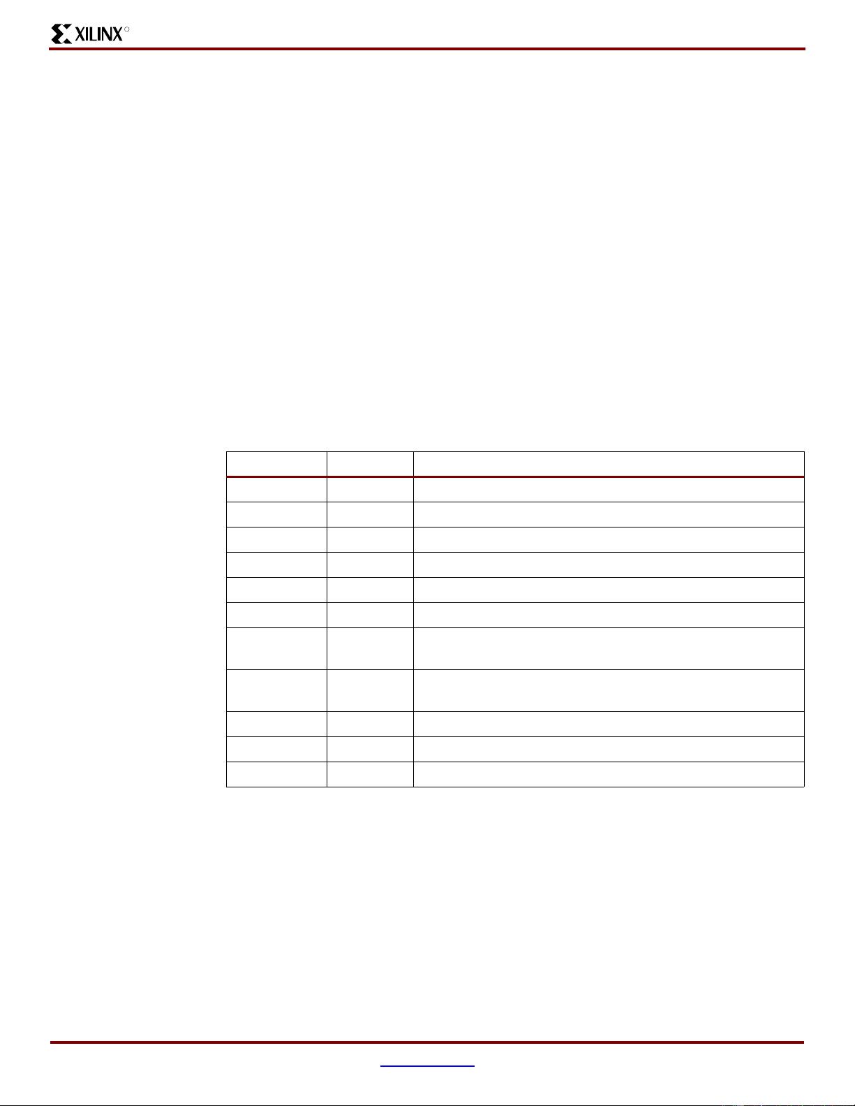
The basic functions of a UART are a microprocessor interface, double buffering of tranmitter
data, frame generation, parity generation, parallel to serial conversion, double buffering of
receiver data, parity checking, serial to parallel conversion. The frame format of used by
UARTs is a low start bit, 5-8 data bits, optional parity bit, and 1 or 2 stop bits. Some UARTs
include modem interface signals. These are pass-through signals which are not done in this
design.
The organization of this application note is to provide a section on the receiver and then the
transmitter.
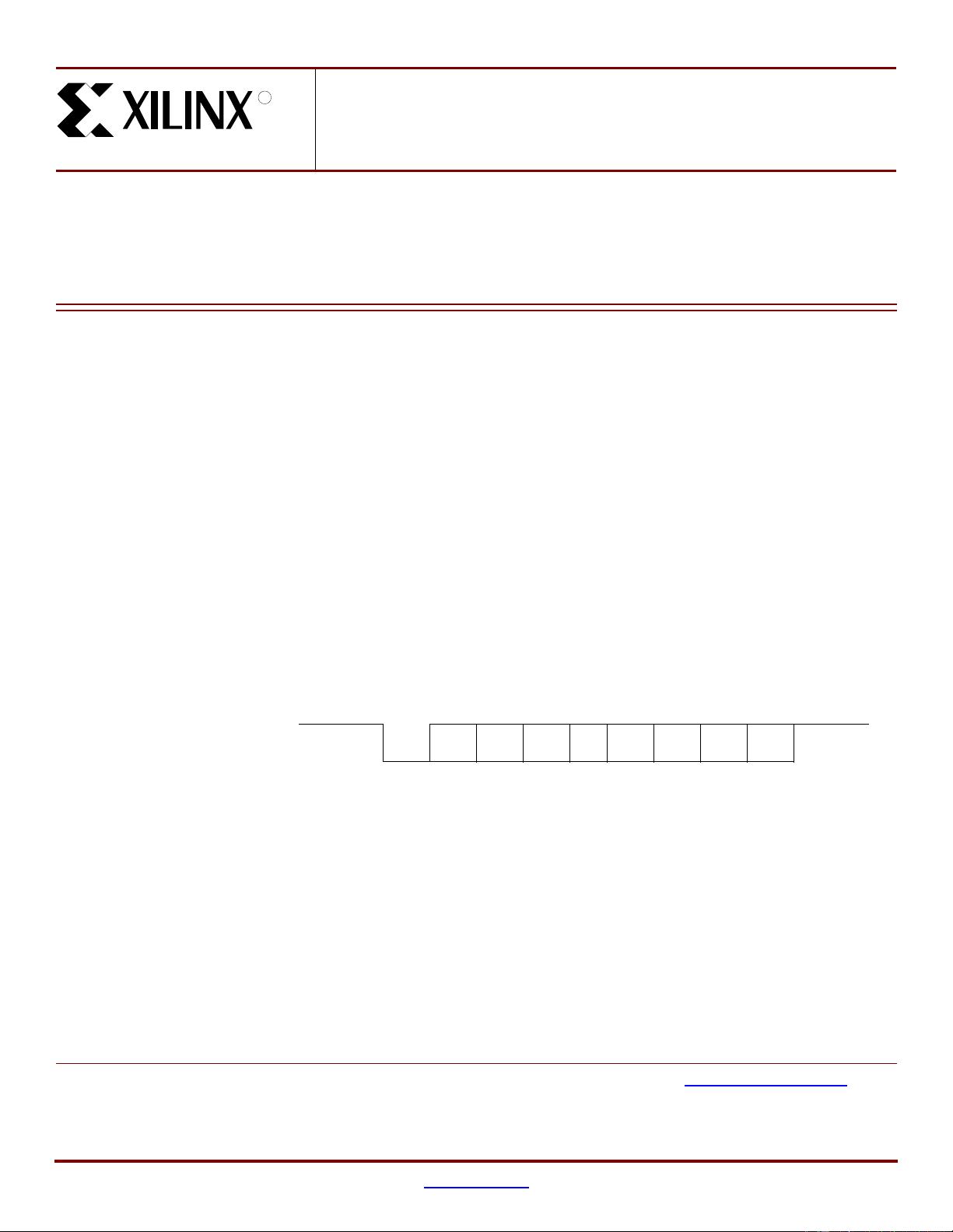
The frame format for data transmitted/received by a UART is given in Figure 1. It consists of a
high idle state of the line. A character is from 5-8 data bits. The start bit isLow and the single
stop bit is High.
Application Note: CPLD
XAPP341 (v1.3) October 1, 2002
UARTs in Xilinx CPLDs
R
Figure 1: Frame Format for UART Transmitted/Received Data
Stop Bit(s)Data BitsStart Bit