没有合适的资源?快使用搜索试试~ 我知道了~
Digital filter design
5星 · 超过95%的资源 需积分: 10 88 下载量 114 浏览量
2007-09-13
18:54:18
上传
评论
收藏 1.52MB PDF 举报
温馨提示
试读
58页
Digital filter design
资源推荐
资源详情
资源评论
Application
ToolBox II: Digital
Filter Design
6
CHAPTER
A hands-on guide to designing and implementing digital filters, with emphasis on
CAD based techniques, and real world applications.
6.1 Introduction 00
6.2 General filter design options 00
6.3 Digital filter methods 00
6.4 Digital filter design options 00
6.5 Digital filter structures and
quantization effects 00
6.6 Digital filter algorithms 00
6.7 Filter design summary 00
6.8 Filter design packages 00
6.9 Specialist filter types 00
6.10 Questions 00
1100
1011
0010
1100
Quadrature Signal Processing
AC Coupling
Correlation
Envelope Detection
Audio Processing
Coding
Speech Processing
Wavelet Transform
Control
Equalisation
Clipping
f
x
Waveform Generation
Linear Scaling
Modulation
Image Processing
Demodulation
Anti Aliasing
Analogue to Digital Conversion
Non-Linear Function
Time-Frequency Transfomation
Frequency Translation
Adaptive Processing
Sample Rate Conversion
Digital Filtering
Digital to Analogue Conversion
You will be hard pressed to find a DSP engineer who designs a digital filter by any means
other than firing up the filter design package on a work station, clicking on a few menu
tabs, entering the filter response required, and then waiting about 10 seconds for the
design to be completed. Multi-coloured graphs showing gain, phase, group delay, impulse
response, number of days shopping left until Christmas, etc, all appear, together with the
filter coefficients, and indeed C or assembler code for your favourite processor (assuming
you have paid for this option!) ready to link into your program.
So, you may well ask, why devote a whole toolbox to digital filter design, if the process
is so straightforward? The answer is that the small number of menu clicks and design
parameters to be entered in the CAD package, are laden with choice. These choices can
have a very significant impact on the performance of the resulting filter as well as influ-
encing how much program and data memory it requires, how many processing cycles it
needs, how stable it is, how accurate it is, and a few other things besides. This ToolBox
thus begins by explaining as briefly as possible what these options are and how to choose
between them.
We then make the assumption that you will be rushing out to buy (well, acquire) a top
of the range filter design package to try all this out for yourself, and therefore give a quick
run through the current options in the market. We could of course be wrong, and you
have a burning desire to design filters by hand. Don’t despair, all the theory you need is in
Chapter 9. (Students who are obliged to learn the theory should not despair – it is bound
to come in handy sometime.)
In the final section, we take a look at some specialist filters that have become favourites
of DSP designers all over the world. They allow clever things to be done with less memory,
fewer cycles, or better response than the standard approaches.
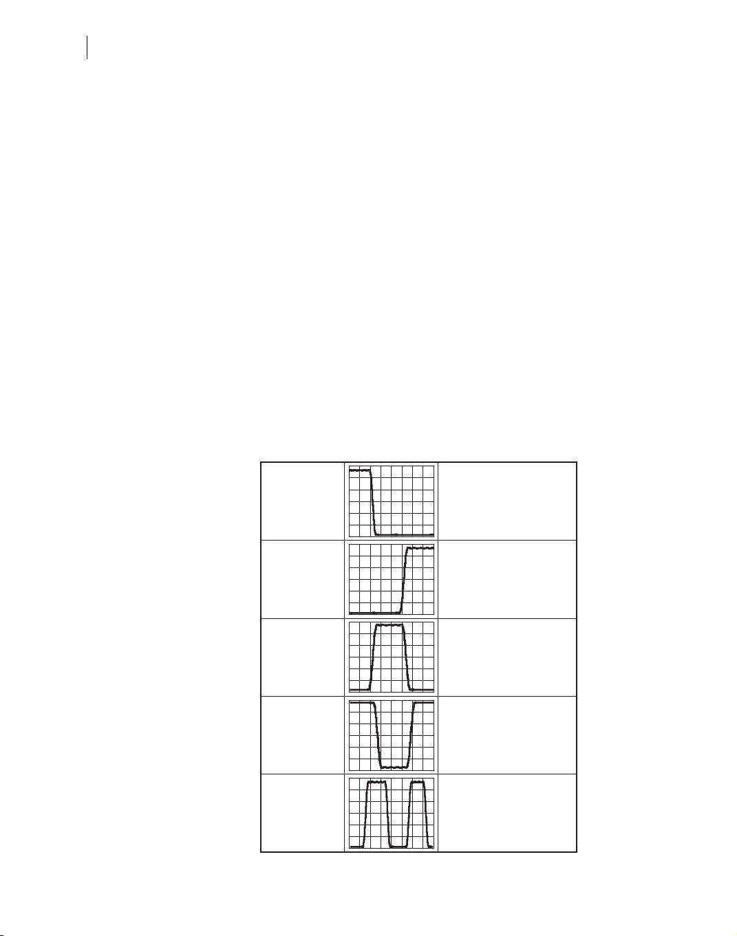
Whether designing a conventional analogue or state-of-the-art digital filter, the first deci-
sion is which type of filter is needed – lowpass, bandpass, highpass, etc. Usually this is self
evident from the application, but with the added flexibility of digital filtering, it is worth
giving this process a little more thought.
For example, suppose you are designing a voice scrambler for covert operations, and
you need to limit the high frequency content to below 3 kHz in order to keep the sampling
rate below 8 kHz. Simple you say, a low pass filter with 3 kHz cut off is needed. However,
there is DC offset on the input sampled signal arising in the A/D converter, which must be
removed as you will be using a mixing process to achieve the scrambling and any DC
component will result in an annoying tone in the audio. OK, so a bandpass filter, say from
Introduction 6.1
General filter design options 339
Basic filter types 6.2.1
General filter design options 6.2
300 Hz to 3 kHz is needed. Maybe, but in order to simplify the mixing process, you want
to make use of some of the quadrature frequency shift algorithms described in ToolBox I.
These require that the input signal is in a quadrature form, which suggests a Hilbert trans-
form filter should be used. But Hilbert transforms filters are best designed as bandpass
filters with symmetry about 1/4 of the sampling frequency. Now the filter we need is a
Hilbert transform filter with 300 Hz to 3700 Hz passband.
Figure 6.1 illustrates the basic filter types that should be considered.
Having chosen the filter type, it is then necessary to define a few basic filter parameters as
outlined in Table 6.1.
Filter gain transfer function
Figure 6.2 shows the transfer function for a generic lowpass filter. This clearly shows the
passband (minimum or zero attenuation) extending from 0 to f
1
, the stopband extending
from f
2
to 0.5f
s
(maximum attenuation) and the transition band (the bit in between). The
passband has a ripple associated with it (no filter has a perfectly flat gain response) which
is usually specified in dB, and the stopband has an attenuation associated with it – again
usually expressed in dB.
340 Chapter 6 ❚ Applications toolbox II: digital filter design
Standard
Average
Raised/root raised cosine
SINC equalizer
Halfband
Lowpass
Standard
AC coupling
Differentiator
Hilbert transform
Highpass
Standard
Hilbert transform
Bandpass
Standard
Notch
Comb
Bandstop
Multiband
Figure 6.1 Basic
filter types
6.2.2 Filter parameters
General filter design options 341
Filter Parameter Notes
Passband(s) Each passband is defined by a start and stop frequency. In the case of lowpass or highpass
filters, some design packages assume a start frequency of 0 Hz (lowpass) or a stop frequency
of f
s
/2 (highpass).
Stopband(s) As for the passband, the stopband is defined by a start and stop frequency. In the case of low
pass or highpass filters some design packages assume a start frequency of 0 Hz (highpass) or
a stop frequency of f
s
/2 (lowpass).
Passband ripple This is usually defined as the maximum acceptable deviation in the gain response of the
passband from unity, expressed in dB (sometimes it is expressed as a percentage).
Stopband attenuation This is defined as the minimum attenuation required in the stopband, expressed in dB.
Transition band Any practical filter must have a finite transition region between passband and stopband where
the attenuation changes with frequency.
Phase response Filters can either have a phase response that changes linearly with frequency (most FIR
filter designs), or non-linearly (most IIR filter designs).
Group delay Group delay is the rate of change of phase with frequency. A linear phase filter will exhibit
constant group delay which ensures minimum distortion of the filtered waveform.
Coefficient length The accuracy with which a digital filter can be implemented is dependent on the precision
with which the filter coefficients (equivalent to component tolerance in analogue filters) and
the data samples are represented. Most CAD packages allow the designer to evaluate the
effects of finite precision sample representation on the filter response.
Implementation method There are a number of algorithms for implementing the same digital filter, each having a
greater or lesser sensitivity to parameters such as word length, quantization noise, stability
and algorithm complexity.
Passband ripple = 20log
10
(1–δ)
Stopband attenuation = 20log
10
(α)
Transition band
α
f
1
f
2
1
(1–δ)
0
Passband edge = f
1
Stopband edge = f
2
Figure 6.2 Generic
Lowpass Filter
Specification
Table 6.1 Filter design parameters
Thus, a possible set of data defining this filter for entry into a filter design package is:
Filter phase/group delay transfer function
The next properties of a filter that must be considered are the phase and group delay
response. Group delay is simply the rate of change of phase with frequency, and is a meas-
ure of how much a given frequency component within a signal will be delayed as it passes
through the filter (Figure 6.3). Ideally, a filter would have zero delay, but this is not physi-
cally possible, and so the delay needs to be taken into account.
A constant group delay through a filter requires that the filter phase response decreases
linearly with frequency (i.e. the rate of change of phase is constant) (Figure 6.4). Such a
filter is known as a linear phase filter.
Constant group delay (linear phase) is particularly important in applications where the
signal wave shape needs to be preserved, such as in high speed data transmission, or in
high fidelity audio or video applications. The effect of non-constant group delay on a data
signal is clearly illustrated in Figure 6.5, and should be avoided if at all possible.
Whilst with analog filters, it is not possible to design a filter with perfectly linear phase
and constant group delay, it is remarkably simple to do so with a digital filter. Usually, this
type of filter goes under the heading of a Finite Impulse Response Filter (FIR) and is dis-
cussed in the next section.
342 Chapter 6 ❚ Applications toolbox II: digital filter design
Comments
Filter type Lowpass
Sampling frequency 8000 Hz Most filter design packages allow the user to specify a
sample rate
Passband edge (1) 0 For a low pass filter, most sensible packages infer that
the lower passband edge is 0 for a low pass filter, but
some do not!
Passband edge (2) 2000 Hz 0.25f
s
Passband ripple 0.1 dB Deviation from unity gain
Stopband edge (1) 3200 Hz 0.4f
s
Stopband edge (2) 4000 Hz 0.5f
s
Again, for a low pass filter, most sensible packages infer
that the upper stopband edge is f
s
/2 for a low pass filter,
but some do not!
Stopband attenuation 40 dB Minimum attenuation required
剩余57页未读,继续阅读
资源评论
- yinuo999942013-05-14恩 英文的 还不错
- thuptenshesrab2018-06-11很好的滤波器设计参考书!
bluecarp
- 粉丝: 5
- 资源: 80
上传资源 快速赚钱
- 我的内容管理 展开
- 我的资源 快来上传第一个资源
- 我的收益 登录查看自己的收益
- 我的积分 登录查看自己的积分
- 我的C币 登录后查看C币余额
- 我的收藏
- 我的下载
- 下载帮助
安全验证
文档复制为VIP权益,开通VIP直接复制
信息提交成功