


GL3523
USB 3.1 Gen 1 Hub Controller
Datasheet
Revision 1.70
Mar. 02, 2017
Genesys Logic, Inc.

GL3523 Datasheet
© 2017 Genesys Logic, Inc. - All rights reserved. Page 2
GLI Confidential
Copyright
Copyright © 2017 Genesys Logic, Inc. All rights reserved. No part of the materials shall be reproduced in any
form or by any means without prior written consent of Genesys Logic, Inc.
Ownership and Title
Genesys Logic, Inc. owns and retains of its right, title and interest in and to all materials provided herein.
Genesys Logic, Inc. reserves all rights, including, but not limited to, all patent rights, trademarks, copyrights and
any other propriety rights. No license is granted hereunder.
Disclaimer
All Materials are provided “as is”. Genesys Logic, Inc. makes no warranties, express, implied or otherwise,
regarding their accuracy, merchantability, fitness for any particular purpose, and non-infringement of intellectual
property. In no event shall Genesys Logic, Inc. be liable for any damages, including, without limitation, any
direct, indirect, consequential, or incidental damages. The materials may contain errors or omissions. Genesys
Logic, Inc. may make changes to the materials or to the products described herein at anytime without notice.
Genesys Logic, Inc.
12F., No. 205, Sec. 3, Beixin Rd., Xindian Dist. 231,
New Taipei City, Taiwan
Tel : (886-2) 8913-1888
Fax : (886-2) 6629-6168
http://www.genesyslogic.com
GL3523 Datasheet
© 2017 Genesys Logic, Inc. - All rights reserved. Page 3
GLI Confidential
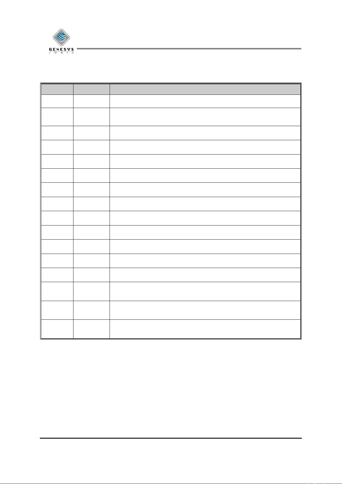
Revision History
Revision
Date
Description
1.00
04/14/2015
Formal release
1.10
05/18/2015
Updated CH4.3.6 &4.3.7, p. 23
Updated CH6.5 On-Chip Power Regulator, p. 29, 30
1.20
06/03/2015
Add SMBus information
1.21
06/09/2015
Modify SMBUS information
1.22
07/29/2015
Update Power Consumption
1.23
09/09/2015
Update description of fast-charging
1.30
09/21/2015
Add GL3523-S and GL3523-Q information
1.40
11/11/2015
Update Section 4.4.6 Port Configuration and Chapter 8 Ordering Information
1.50
02/18/2016
Modify the description for CHIPEN pin
1.51
03/25/2016
Rename BGA as VFBGA
1.52
05/11/2016
Correct the pin description of OVCUR pins, p. 14
1.60
06/22/2016
Correct the pin description of V5, p. 15
1.61
06/28/2016
Update power consumption, p. 43
1.62
11/17/2016
Modify the pin description of OVCUR pins, p.14, 23, and 29
Add description for power consumption, p.43
1.63
03/02/2017
Correct the pin description
Add V5_CC pin description, p. 25
1.70
03/02/2017
Update GL3523-S Pin-out diagram, P. 17~21
Remove GL3523-Q

GL3523 Datasheet
© 2017 Genesys Logic, Inc. - All rights reserved. Page 4
GLI Confidential
Table of Contents
CHAPTER 1 GENERAL DESCRIPTION ......................................................................... 8
CHAPTER 2 FEATURES .................................................................................................... 8
CHAPTER 3 PIN ASSIGNMENT..................................................................................... 11
3.1 GL3523 Pin-out Diagram ............................................................................................ 11
3.2 GL3523 Pin Descriptions ............................................................................................ 14
3.3 GL3523-S Series Pin-out Diagram ............................................................................. 17
3.4 GL3523-S Pin Descriptions ......................................................................................... 22
CHAPTER 4 FUNCTION DESCRIPTION ..................................................................... 26
4.1 GL3523 Functional Block ........................................................................................... 26
4.2 GL3523-S Functional Block ........................................................................................ 27
4.3 General Description ..................................................................................................... 28
4.3.1 USB 2.0 USPORT Transceiver ........................................................................... 28
4.3.2 USB 3.1 Gen 1 USPORT Transceiver ................................................................ 28
4.3.3 PLL (Phase Lock Loop) ...................................................................................... 28
4.3.4 Regulator .............................................................................................................. 28
4.3.5 SPI Engine ............................................................................................................ 28
4.3.6 RAM/ROM/CPU.................................................................................................. 28
4.3.7 UTMI (USB 2.0 Transceiver Microcell Interface) ............................................ 28
4.3.8 SIE (Serial Interface Engine) .............................................................................. 28
4.3.9 Control/Status Register ....................................................................................... 28
4.3.10 Power Management Engine .............................................................................. 28
4.3.11 Router/Aggregator Engine ................................................................................ 29
4.3.12 REPEATER ....................................................................................................... 29
4.3.13 TT ........................................................................................................................ 29
4.3.14 CDP Control Logic ............................................................................................ 30
4.3.15 USB 3.1 Gen 1/USB 2.0 DSPORT Transceiver ............................................... 30
4.4 Configuration and I/O Settings .................................................................................. 31
4.4.1 RESET Setting ..................................................................................................... 31
4.4.2 PGANG Setting .................................................................................................... 32

GL3523 Datasheet
© 2017 Genesys Logic, Inc. - All rights reserved. Page 5
GLI Confidential
4.4.3 SELF/BUS Power Setting ................................................................................... 33
4.4.4 LED Connections ................................................................................................. 33
4.4.5 Power Switch Enable Polarity ............................................................................ 34
4.4.6 Port Configuration .............................................................................................. 34
4.4.7 Non-removable Port Setting ............................................................................... 34
4.4.8 SMBUS Mode (SMBUS Slave Address=0x25) .................................................. 34
CHAPTER 5 FAST CHARGING SUPPORT .................................................................. 35
5.1 Introduction to Battery Charging Specification Rev.1.2 ......................................... 35
5.2 Standard Downstream Port (SDP) ............................................................................. 35
5.3 Charging Downstream Port (CDP) ............................................................................ 35
5.4 Dedicated Charging Port (DCP) ................................................................................ 36
5.5 ACA-Dock .................................................................................................................... 36
5.6 Apple and Samsung Devices ....................................................................................... 36
5.7 Charging Downstream Port Configuration .............................................................. 36
CHAPTER 6 ELECTRICAL CHARACTERISTICS ..................................................... 37
6.1 Maximum Ratings ....................................................................................................... 37
6.2 Operating Ranges ........................................................................................................ 37
6.3 DC Characteristics ...................................................................................................... 38
6.3.1 DC Characteristics except USB Signals ............................................................. 38
6.3.2 USB 2.0 Interface DC Characteristics ............................................................... 38
6.3.3 USB 3.1 Gen 1 Interface DC Characteristics .................................................... 38
6.4 Power Consumption .................................................................................................... 39
6.5 On-Chip Power Regulator .......................................................................................... 40
6.5.1 5V to 3.3V Regulator ........................................................................................... 40
6.5.2 5V to 1.2V Regulator ........................................................................................... 41
6.6 External Clock ............................................................................................................. 41
CHAPTER 7 PACKAGE DIMENSION ........................................................................... 42
CHAPTER 8 ORDERING INFORMATION................................................................... 47


