TOF lidar方案介绍
需积分: 40 23 浏览量
2020-10-12
15:25:48
上传
评论
收藏 150KB PDF 举报
TX Start
RX
Optical
Time-of-Flight
(ToF)
System
Stop
MSP430
Microcontroller
Launch Pad
Laser Driver
Transimpedance
Amplifier
Comparator
TDC7201
Laser Diode
Photo Diode
Optional
Alternative
START
Monitor
Output
COMMON START
START
SPI
STOP
50
FO
FO
OPA858
TLV3501
TIDA-060025 Board
1
SBOA337–February 2020
Submit Documentation Feedback
Copyright © 2020, Texas Instruments Incorporated
Time of Flight and LIDAR - Optical Front End Design
Anthony Vaughan
Time of Flight and LIDAR - Optical Front End Design
Anthony Vaughan
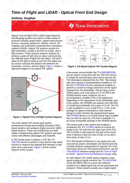
Optical Time-of-Flight (ToF) LIDAR (Light Detection
and Ranging) systems are used in a wide variety of
products including range finders, speed measurement
devices, surveying equipment, robotics, drones, 3D
mapping, and automotive advanced driver assistance
systems (ADAS). Optical ToF systems consist of a
light transmitter, usually in the form of a laser, and a
light receiver. These systems measure distance by
emitting a pulse of light onto an object and receiving
the reflected pulse of light from the object. The time it
takes for the light to travel to and from the object can
be used to calculate the distance the between the
transmitter, receiver, and the object. Figure 1 shows a
high-level diagram of an optical ToF system.
Figure 1. Optical Time-of-Flight System Diagram
Two main optical ToF receive path system
architectures include time-to-digital converter (TDC)
based systems and analog-to-digital converter (ADC)
based systems. These two architectures are both
viable in implementing optical ToF systems and each
comes with different advantages and tradeoffs.
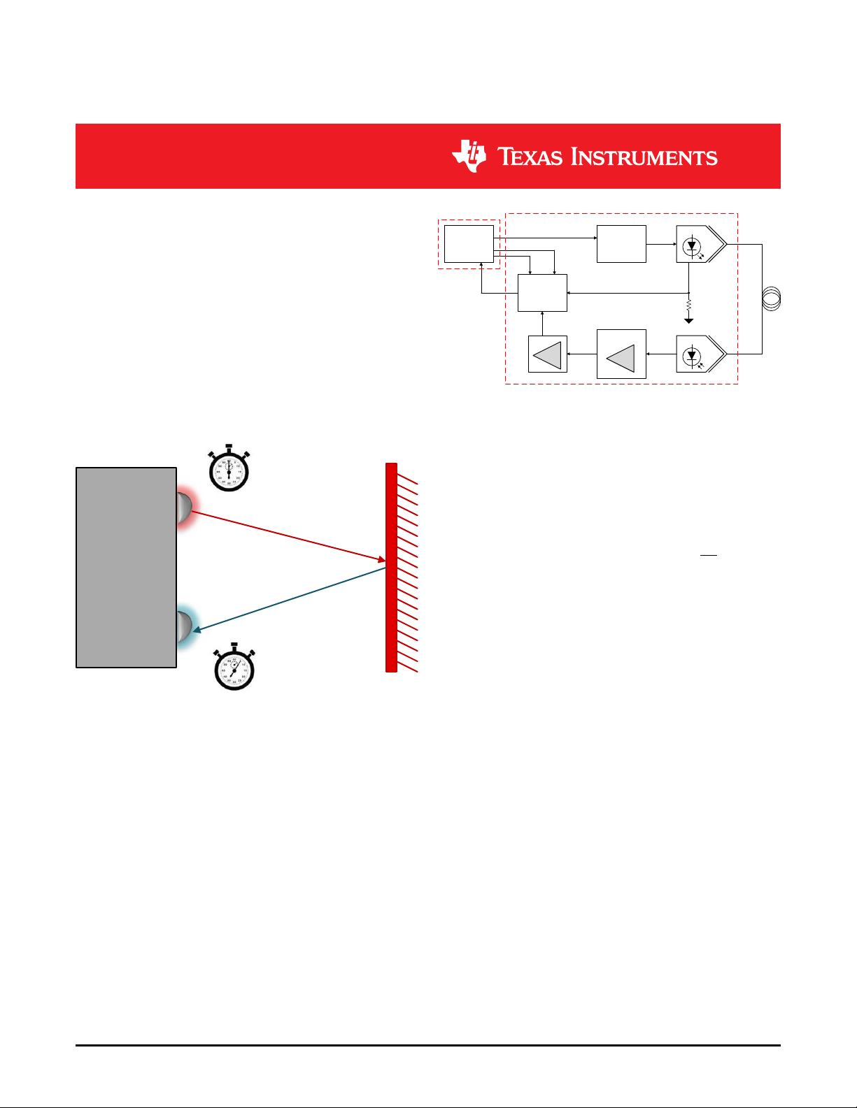
A TDC-based system employs a TDC like TI’s
TDC7201 device to perform a very precise stop watch
function to measure the elapsed time between a start
pulse and a stop pulse. Figure 2 shows a block
diagram of this system.
Figure 2. DC-Based Optical ToF System Diagram
A low-power microcontroller like TI’s MSP430F5529
can be used in conjunction with the TDC7201 device
to initiate the transmit laser pulse and to process the
ToF information collected from the TDC. The receive
path also requires a transimpedance amplifier or TIA
like the TI OPA858 5.5-GHz operational amplifier to
perform a current-to-voltage conversion on the signal
received from the photodiode. The low bias current
CMOS inputs, and a low noise of 2.5 nV/√Hz of the
OPA858 device make it ideal for use as a
transimpedance amplifier (TIA) in this application.
Depending on the capacitance of the photodiode used
in the system, the OPA858 can achieve over 250 MHz
of closed-loop bandwidth with a gain of 10 kΩ. The TIA
is also available in a very small 2 mm × 2 mm, 8-pin
package for space-constrained or multi-channel
designs to help minimize the required board space.
The OPA855 device is an 8-GHz bipolar input amplifier
that can also be used as a TIA that is available in a
pin-to-pin compatible package to the OPA858 device.
The receive path in this system also employs a
comparator like TI’s TLV3501 device to receive the
output of the TIA and drive the stop input of the TDC.
The TLV3501 is well suited for this part of the circuit
since it features a fast rise time of only 1.5 ns and a
short delay of only 4.5 ns.
This TDC-based architecture is very good when low
cost and low power consumption are desired and only
a simple distance measurement is required. For more
information about the TDC-based architecture, see the
TIDA-060025 reference design and the Time of Flight
& LIDAR - Optical Front End Reference Design video.
An ADC-based ToF LIDAR system employs a high-
speed analog-to-digital converter like TI’s ADC34J45
14-bit 160 MSPS ADC to convert the reflected
waveform to a digital signal that can be processed and
analyzed. These systems usually use a digital signal


评论0
最新资源