


AN10835
LPC2000 secondary bootloader for code update using IAP
Rev. 01 — 26 May 2009 Application note
Document information
Info Content
Keywords LPC2000, Secondary bootloader, IAP, Code update
Abstract This application note describes the design and implementation of a
secondary bootloader which can update the user application code in on-
chip flash via UART with 1K XMODEM protocol, SD/MMC with file
system, EEPROM with I2C interface and CAN interface using IAP (In-
Application Programming).

NXP Semiconductors
AN10835
LPC2000 secondary bootloader for code update using IAP
Revision history
Rev Date Description
01 20090526 Initial version
Contact information
For additional information, please visit: http://www.nxp.com
For sales office addresses, please send an email to: salesaddresses@nxp.com
AN10835_1 © NXP B.V. 2009. All rights reserved.
Application note Rev. 01 — 26 May 2009 2 of 21

NXP Semiconductors
AN10835
LPC2000 secondary bootloader for code update using IAP
1. Introduction
In most LPC2000 devices, the primary bootloader is the firmware which resides in the
Boot Block and is executed every time the part is powered on or reset. The secondary
bootloader in this document refers to a user-defined application that provides the user
with an option to update the code or execute the previously programmed code.
In Application Programming (IAP executes erase and write operations on the on-chip
flash memory, as directed by the end-user application code.
Code update is a typical application of IAP. This document describes four secondary
bootloaders using different interfaces (UART using the 1K XMODEM protocol, SD/MMC
using a FAT file system, I2C interfaced to EEPROM and CAN).
2. LPC2000 flash programming
2.1 Sector description
The IAP commands operate on a sector-by-sector basis. This means that in order to
make any modifications (even if it is just one byte) in a particular sector, the entire sector
must be erased.
The user application and the secondary bootloader share the same on-chip flash space.
This means that the user’s application code should not be placed inside any of the
sectors on which the bootloader resides. Therefore, the application should be erased and
programmed in sectors – separate from the bootloader.
IAP, ISP, and RealMonitor routines are located in the primary bootloader (Boot block).
The boot block is present at addresses 0x0007 E000 to 0x0007 FFFF (8 kB) in all
devices. Depending on the device, not all of the flash is available to the user. This is the
case if the part contains 512 kB of flash. Rather than having 512 kB available, the user
will only have 504 kB available for the application. In devices that have less than 512 kB
flash available, please refer to the respective user manuals.
Fig 1
indicates the correspondence between sector numbers and memory addresses for
LPC23xx devices containing 128, 256 and 512 kB of flash respectively. For other
LPC2000 devices please refer to the user manual.
AN10835_1 © NXP B.V. 2009. All rights reserved.
Application note Rev. 01 — 26 May 2009 3 of 21

NXP Semiconductors
AN10835
LPC2000 secondary bootloader for code update using IAP
Fig 1. Sectors in LPC2300 devices
2.2 In Application Programming (IAP)
2.2.1 IAP introduction
A boot code 8 kB in size is programmed into the on-chip flash after factory. The boot
code controls initial operation after reset and also provides the means to accomplish
programming of the flash memory. This could be initial programming of a blank device,
erasure and re-programming of a previously programmed device, or programming of the
Flash memory by the application program in a running system.
In Application Programming (IAP) executes erase and write operations on the on-chip
flash memory, as directed by the end-user application code.
2.2.2 IAP application
Using IAP, users can update the application code by various communication interfaces
such as UART, USB or Ethernet. Flash sectors that aren’t used for the secondary
bootloader or the user application may be used as non-volatile data storage.
While the application is running, the user can update some portion of the code using IAP
commands which we call “online code updates”. It is not necessary to power off or even
to remove the chip from the board to have it serviced by some commercial programming
tools.
Having the device work as data storage, PCB costs and sizes can be reduced. Caution is
however advised in handling data storage sectors. Since sectors functioning as data
storage can be erased, no application code should be contained in these sectors.
Frequent erasing and programming will reduce the flash’s lifecycle. The LPC2000
provides a minimum of 10,000 write/erase cycles and 10 years of data retention.
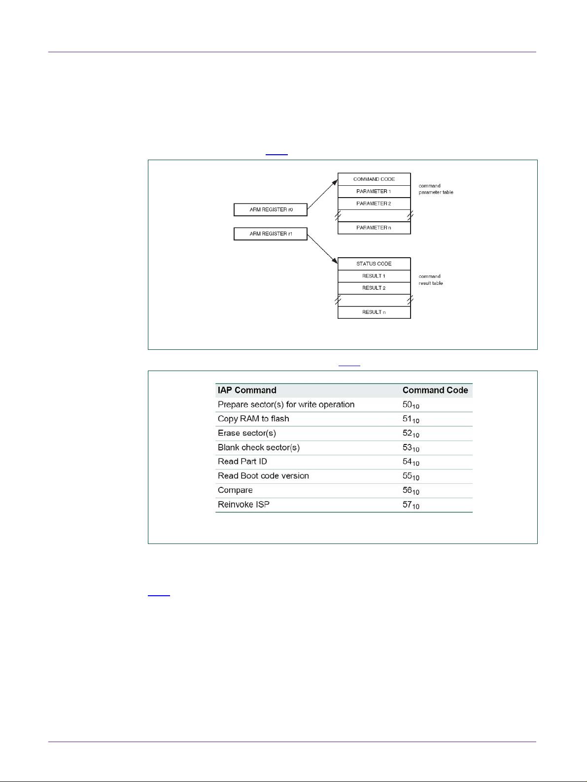
2.2.3 IAP commands
For in application programming, the IAP routine should be called using a word sized
pointer that has been loaded into register r0, which is pointing to memory (on-chip RAM)
AN10835_1 © NXP B.V. 2009. All rights reserved.
Application note Rev. 01 — 26 May 2009 4 of 21
NXP Semiconductors
AN10835
LPC2000 secondary bootloader for code update using IAP
containing the command code and its parameters. Register r1 contains the results of the
IAP command returned by a pointer (pointing to a table). The user can reuse the
command table for the results by passing the same pointers into registers r0 and r1.
Ensure that the results table is large enough to store all the results coming from the IAP
command issued. Refer to Fig 2
.
Fig 2. IAP parameter passing
The IAP commands and codes are listed in Fig 3.
Fig 3. IAP command summary
For detailed information, please refer to the LPC2000 user manual.
2.2.4 Using IAP
Fig 4 shows the necessary steps to perform the flash programming using IAP.
AN10835_1 © NXP B.V. 2009. All rights reserved.
Application note Rev. 01 — 26 May 2009 5 of 21


- 1
- 2
- 3
- 4
- 5
- 6
前往页