


AN10866
LPC1700 secondary USB bootloader
Rev. 3 — 7 February 2013
Application note
Document information
Info
Content
Keywords
LPC1700, Secondary USB Bootloader, ISP, IAP
Abstract
This application note describes how to add a custom secondary USB
bootloader to a LPC1700 series microcontroller.

NXP Semiconductors
AN10866
LPC1700 secondary USB bootloader
AN10866
All information provided in this document is subject to legal disclaimers.
© NXP B.V. 2013. All rights reserved.
Application note
Rev. 3 — 7 February 2013
2 of 19
Contact information
For additional information, please visit:
http://www.nxp.com
For sales office addresses, please send an email to:
salesaddresses@nxp.com
Revision history
Rev
Date
Description
3
20130207
• Modified code: IAP clock parameter is changed to SystemFrequency/1000.
This is required to ensure correct flash program and erase time.
2
20100921
• Updated on how the USB Bootloader executes the user application.
• Updated bootloader and user application location figure.
• Added the CRP define statement for the “Asm” target options.
• Removed the CRP binary/hex comparison section.
1
20090908
• Initial version.

NXP Semiconductors
AN10866
LPC1700 secondary USB bootloader
AN10866
All information provided in this document is subject to legal disclaimers.
© NXP B.V. 2013. All rights reserved.
Application note
Rev. 3 — 7 February 2013
3 of 19
1. Introduction
NXP’s LPC1700 microcontrollers provide the user a convenient way to update the flash
contents in the field for bug fixes or product updates. This can be achieved using the
following two methods:
• In-System Programming: In-System programming (ISP) is programming or
reprogramming the on-chip flash memory, using the boot loader software and
UART0 serial port. This can be done when the part resides in the end-user board.
• In Application Programming: In-Application (IAP) programming is performing erase
and write operation on the on-chip flash memory, as directed by the end-user
application code.
A secondary bootloader is a piece of code which allows a user application code to be
downloaded using alternative channels other than the standard UART0 used by the
primary bootloader (on-chip). The primary bootloader is the firmware that resides in a
microcontroller’s boot ROM block and is executed on power-up and resets. After the boot
ROM’s execution the secondary bootloader is executed. The secondary bootloader in
turn will then execute the end-user application.
This application note uses USB as an example for developing a secondary bootloader on
a LPC1700 series microcontroller.
2. Requirements
2.1 Hardware requirements
The secondary USB Bootloader application has been developed and tested using a:
• Keil’s MCB1700 development board
• MS Windows-based workstation with an available USB port.
Fig 1. MCB1700 featuring a LPC176x series microcontroller

NXP Semiconductors
AN10866
LPC1700 secondary USB bootloader
AN10866
All information provided in this document is subject to legal disclaimers.
© NXP B.V. 2013. All rights reserved.
Application note
Rev. 3 — 7 February 2013
4 of 19
2.1.1 Programming
Programming the bootloader can be done using Keil’s U-LINK JTAG/SWD module.
However, as an additional option the LPC1700’s ISP programming functionality can be
used instead. To program using the ISP protocol an RS-232 serial cable is required and
a free ISP programming tool is available from FlashMagic at:
http://www.nxp.com/flashmagictool.com/
2.1.2 Jumper settings
In order to use the USB device functionality, ensure that the USB’s D+ and D- jumpers
are both set to the “DEVICE” header pins as shown in
Fig 1.
2.1.3 USB cable
A USB-A to USB-B cable is required to power and connect the windows workstation to
the MCB1700 development board.
2.1.4 Secondary Bootloader’s entry mechanism
Having an entry pin grounded during reset will cause the secondary USB bootloader to
enter its programming mode. For convenience, P1.20 is used by default because it is
wired to the center button of the joy-stick as shown in
Fig 1.
By keeping the MCB1700’s joystick button pressed during a reset will cause the
secondary USB bootloader to enter it programming mode
1
.
2.2 Software requirements
An evaluation version of Keil’s uVision3 is sufficient to compile the secondary USB
bootloader and the sample user applications.
The secondary USB bootloader has been developed and tested using a MS windows-
based workstation.
3. Flashing the LPC1700
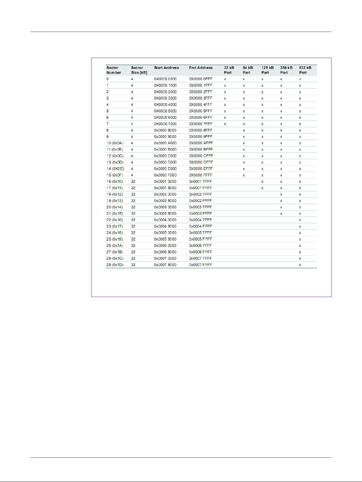
3.1 Flash sectors
Depending on the LPC1700 part variant, the user has up to 512kB (Bytes) of on-chip
flash available. This user flash space is divided up into sectors.
In order to make any modifications (even if it is just one byte) to a particular sector, the
entire sector must be first erased and then (re)written.
1. 1. Depends on the CRP value.
NXP Semiconductors
AN10866
LPC1700 secondary USB bootloader
AN10866
All information provided in this document is subject to legal disclaimers.
© NXP B.V. 2013. All rights reserved.
Application note
Rev. 3 — 7 February 2013
5 of 19
(1) Flash space varies in size, depending on the part number
Fig 2. Flash sectors
Both, the secondary USB bootloader and the user application reside in flash. Therefore,
for the secondary USB bootloader to flash the user application without modifying any of
its own code, the user application should be flashed starting the next available sector.
Additionally, any flash sectors that do not contain any code may be used for data storage
using the IAP commands.
3.2 ISP
ISP (In-system Programming) is supported in all LPC1700 series microcontrollers. ISP
programming can be used to flash the microcontroller while it is in the end-user system.
The ISP protocol consists of commands that are sent in ASCII format via the UART0
interface. To enter ISP mode, P2.10 needs to be low during a reset. The ISP routines are
located in the primary bootloader. Therefore, during a reset, it is possible to enter ISP
mode before entering the secondary bootloader.
A detailed description of the ISP commands can be found in the LPC1700 user manual.


评论0
最新资源