PSoC® Creator™ Example Project
Cypress Semiconductor Corporation • 198 Champion Court • San Jose, CA 95134-1709 • 408-943-2600
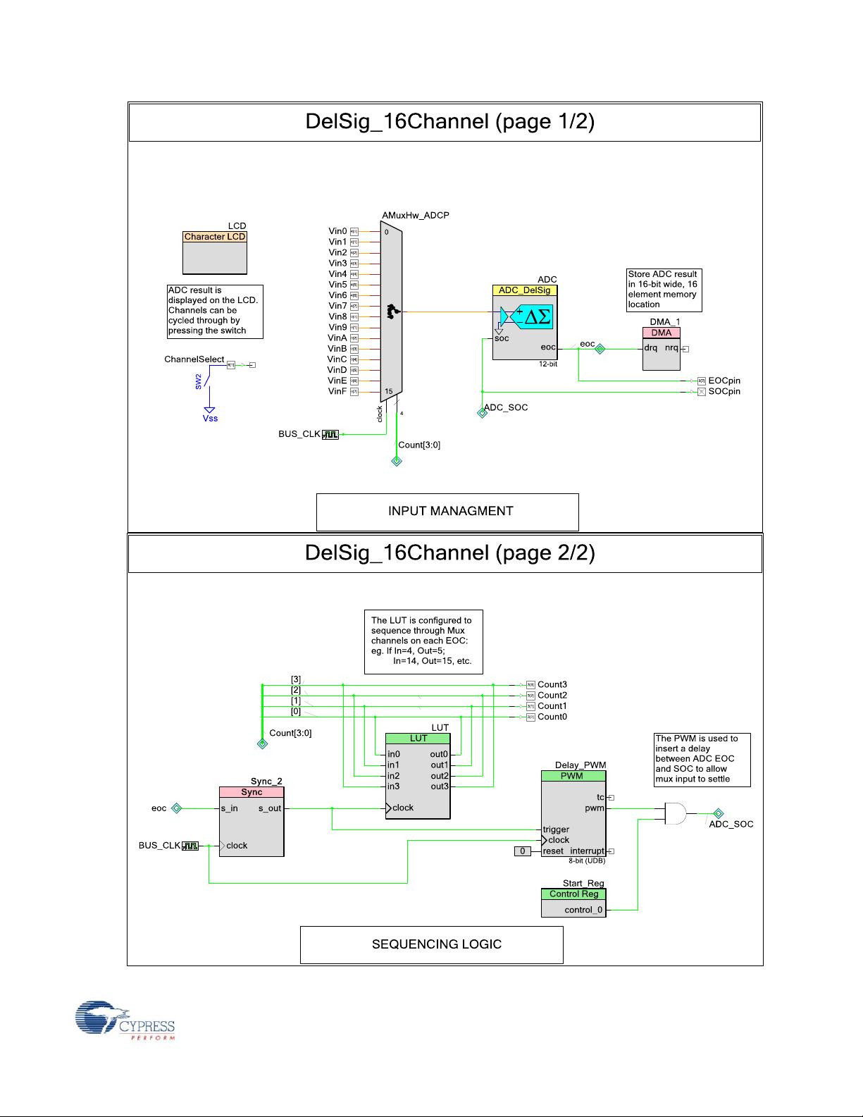
Features
12-bit Delta-Sigma ADC with 16 multiplexed single-ended inputs.
The Analog Mux and ADC are controlled in hardware and ADC results stored in memory
using DMA – No firmware intervention.
Switch can be used to cycle through readings displayed on LCD.
General Description
This example project is also a PSoC Creator starter design. It uses the Delta Sigma ADC, DMA,
and other hardware to sequence, sample, and store 16-channels of input data in memory without
CPU intervention.
Development Kit Configuration
The following configuration instructions provide a guideline to test this design. For simplicity, the
instructions describe the stepwise process to follow when testing this design with the PSoC
Development Kit (CY8CKIT-001) board, but can be generalized for the PSoC 3 Development Kit
(CY8CKIT-030) as well.
1. Set LCD power jumper J12 to ON position, assign SW3 to the 5V position, and leave the
rest of the board at default configuration.
2. Observe the mux channel select signals P3[3:0], the ADC SOC P3[6] and the ADC EOC
P3[7] on an oscilloscope.
3. Connect P6[1] to SW2 on the board, and ensure that a character LCD is connected to
P2[6:0].
4. If testing the project with Analog inputs, connect the first 8 to P4[7:0] and the other 8 to
P0[7:0]. Ensure that these voltages are between 0 and 2.048V – the input range set for
the ADC.
5. Build the DelSig_16Channel project and then program the hex file to the PSoC device
using the MiniProg3. After programming is complete, disconnect the MiniProg3.
6. Reset the PSoC device.
DelSig_16Channel Example Project
1.00