AMT49406-Datasheet.pdf
需积分: 50 200 浏览量
2020-04-08
18:08:32
上传
评论
收藏 1.12MB PDF 举报

The AMT49406 is a 3-phase, sensorless, brushless DC (BLDC)
motor driver (gate driver) which can operate from 5.5 to 50 V.
A field-oriented control (FOC) algorithm is fully integrated to
achieve the best efficiency and acoustic noise performance. The
device optimizes the motor startup performance in a stationary
condition, a windmill condition, and even in a reverse windmill
condition.
Motor speed is controlled through analog, PWM, or CLOCK
input. Closed-loop speed control is optional, and RPM-to-clock
frequency ratio is programmable.
A simple I
2
C interface is provided for setting motor-rated
voltage, rated current, rated speed, resistance, and startup
profiles.
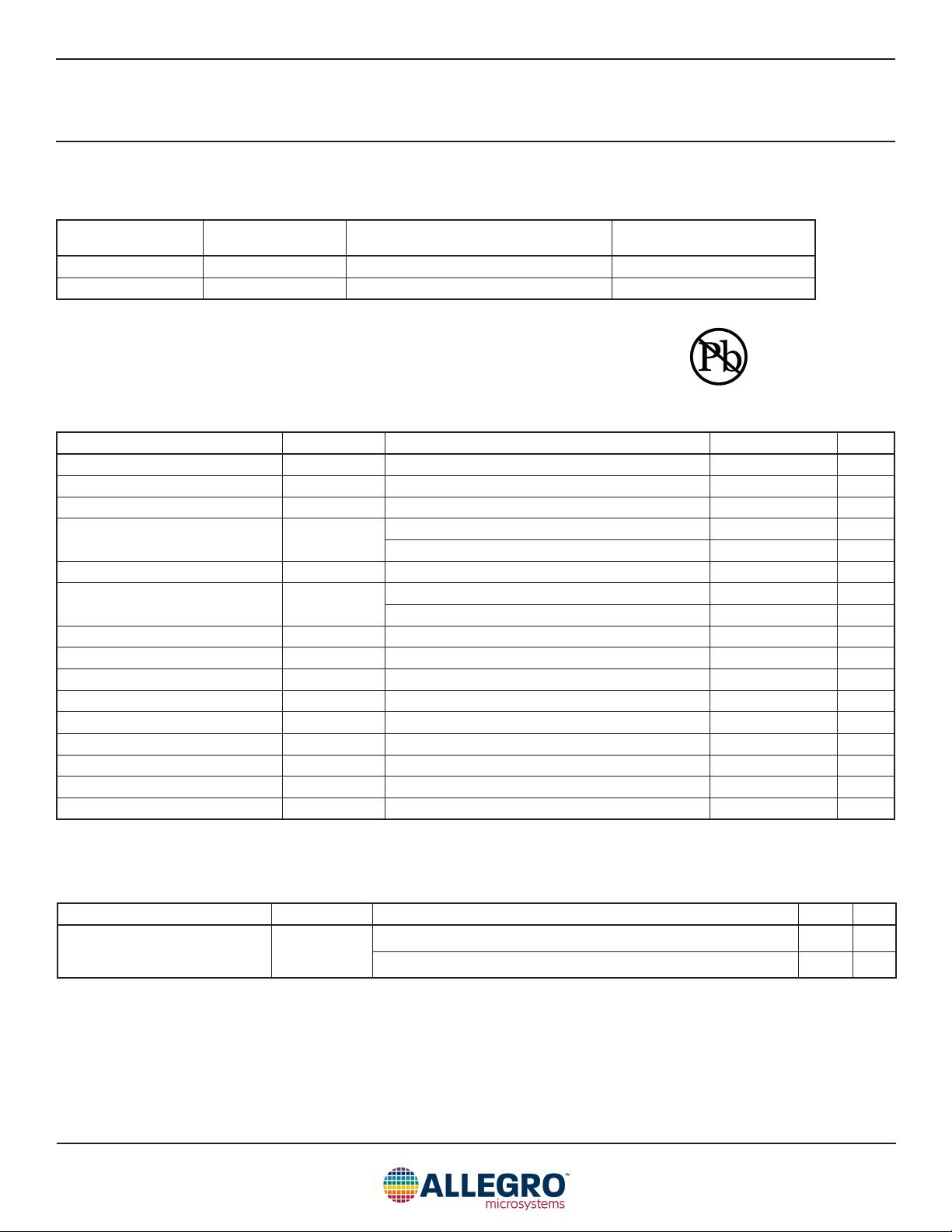
The AMT49406 is available in a 24-contact 4 mm × 4 mm QFN
with exposed thermal pad (suffix ES) and a 24-lead TSSOP
with exposed thermal pad (suffix LP). These packages are lead
(Pb) free, with 100% matte-tin leadframe plating.
AMT49406-DS, Rev. 1
MCO-0000542
• Code-free sensorless field-oriented control (FOC)
• Proprietary non-reverse fast startup
• Soft-On Soft-Off (SOSO) for quiet operation
• Analog / PWM / Clock mode speed control
• Closed-loop speed control
• Configurable current limit
• Windmill startup operation
• Lock detection
• Short-circuit protection (OCP)
• Brake and direction inputs
50 V Code-Free FOC BLDC Motor Controller
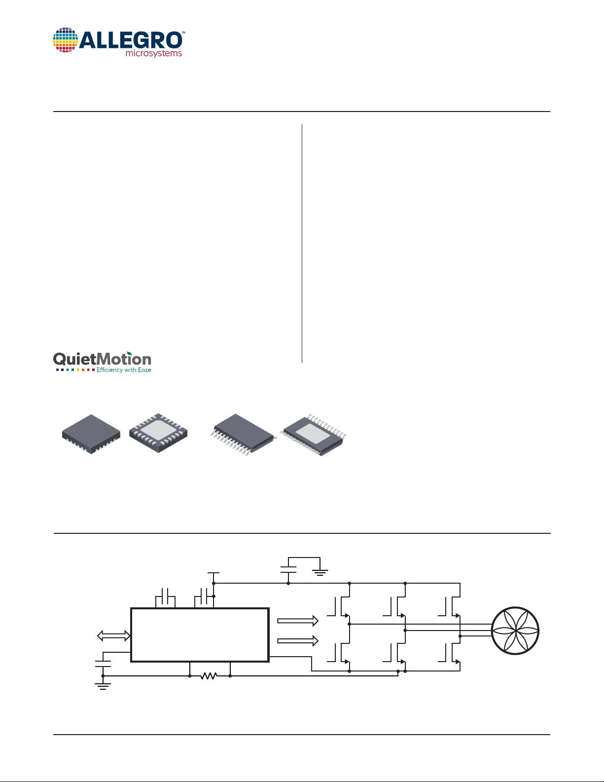
PACKAGES
Figure 1: Typical Application
Not to scale
AMT49406
FEATURES AND BENEFITS DESCRIPTION
January 24, 2019
AMT49406
CP1 CP2
SENN
VREG
SENP
VCP VBB
GHx
GLx
LSS
VBB
FG
SPD
FAULT
DIR
BRK
0.1 µF 0.1 µF
0.22 µF
• Ceiling fans
• Pedestal fans
• Bathroom exhaust fans
• Home appliance fans and pumps
APPLICATIONS
24-contact QFN
with exposed thermal pad
4 mm × 4 mm × 0.75 mm
(ES package)
24-lead TSSOP
with exposed thermal pad
(LP package)


剩余18页未读,继续阅读
资源评论


