没有合适的资源?快使用搜索试试~ 我知道了~
温馨提示
试读
17页
In AM335x the ROM code serves as the bootstrap loader, sometimes referred to as the Initial Program Loader (IPL)or the Primary Program Loader (PPL). The booting is completed in two consecutive stages by U-Bootbinaries.The binary for the 1st U-Boot stage is referred to as the Secondary Program Loader (SPL) or the MLO. The binaryfor the 2nd U-Boot stage is simply referred to as U-Boot.SPL is a non-interactive loader and is a specially builtversion of U-Boot. It is built concurrently when building U-Boot.
资源推荐
资源详情
资源评论
AM335x U-Boot User's Guide
1
AM335x U-Boot User's Guide
Linux PSP
U-Boot
In AM335x the ROM code serves as the bootstrap loader, sometimes referred to as the Initial Program Loader (IPL)
or the Primary Program Loader (PPL). The booting is completed in two consecutive stages by U-Boot
[1]
binaries.
The binary for the 1st U-Boot stage is referred to as the Secondary Program Loader (SPL) or the MLO. The binary
for the 2nd U-Boot stage is simply referred to as U-Boot. SPL is a non-interactive loader and is a specially built
version of U-Boot. It is built concurrently when building U-Boot.
The ROM code can load the SPL image from any of the following devices
€€ Memory devices non XIP (NAND/SDMMC)
The image should have the Image header. The image header is of length 8 byte which has the load address(Entry
point) and the size of the image to be copied. RBL would copy the image, whose size is given by the length field in
the image header, from the device and loads into the internal memory address specified in the load address field of
Image header.
€€ Peripheral devices (UART)
RBL loads the image to the internal memory address 0x402f0400 and executes it. No Image Header present.
Two stage U-Boot design
This section gives an overview of the two stage U-Boot approach adopted for AM335X.
The size of the internal RAM in AM335X is 128KB out of which 18KB at the end is used by the ROM code. Also, 1
KB at the start (0x402f0000 - 0x402f0400) is secure and it cannot be accessed This places a limit of 109KB on the
size of the U-Boot binary which the ROM code can transfer to the internal RAM and use as an initial stack before
initialization of DRAM.
Since it is not possible to squeeze in all the functionality that is normally expected from U-Boot in < 110KB (after
setting aside some space for stack, heap etc) a two stage approach has been adopted. Initial stage initalize only the
required boot devices (NAND, MMC, I2C etc); 2nd full stage initall all other devices (ethernet, timers, clocks etc).
The 1st binary is generated MLO and the 2nd stage is generated as u-boot.img.
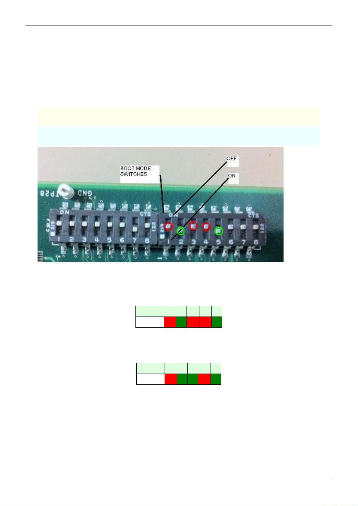
NOTE
*When using memory boot (NAND) a header needs to be attached to the SPL binary indicating the load address and
the size of the image. SPI boot additionally requires endian conversion before flashing the image.
€€ When using peripheral boot (UART) there can be no header as the load address is fixed.
AM335x U-Boot User's Guide
2
Updated Toolchain
Starting with Sitara Linux SDK 6.0 the location of the toolchain has changed and for non ARM 9 devices a new
Linaro based toolchain will be used. Details about the change in toolchain location can be found here
[2]
. Also details
about the switch to Linaro can be found here
[3]
.
AM18x users are not affected by the switch to Linaro. Therefore, any references to the Linaro toolchain prefix
"arm-linux-gnueabihf-" should be replaced with "arm-arago-linux-gnueabi-".
Building U-Boot
Prerequisite
GNU toolchain for ARM processors from Arago is recommended. Arago Toolchain can be found in the linux-devkit
directory of the SDK here
[4]
NOTE
Below steps assumes that the release package is extracted inside directory represented as $AM335x-PSP-DIR
Change to the base of the U-Boot directory.
$ cd ./AM335x-LINUX-PSP-MM.mm.pp.bb/src/u-boot/u-boot-MM.mm.pp.bb
Building into a separate object directory with the "O=" parameter to make is strongly recommended.
Commands
$ [ -d ./am335x ] && rm -rf ./am335x
$ make O=am335x CROSS_COMPILE=arm-linux-gnueabihf- ARCH=arm am335x_evm
This will generate two binaries in the am335x directory, MLO and u-boot.img along with other intermediate binaries
that may be needed in some cases (see below).
Host configuration
Serial port configuration
Connect a serial cable from the serial port of the EVM (serial port is next to the power switch) to the COM port on
either the Windows machine or Linux host depending on where you'll be running the serial terminal software.
For correct operation the serial terminal software should be configured with the following settings:
*Baud rate: 115,200
*Data bits: 8
*Parity: None
*Stop bits: 1
*Flow control: None
NOTE
If Teraterm is being used, ensure that the latest version (4.67 is the latest version as of writing this user guide) of
Teraterm is installed. The implementation of the Kermit protocol in Teraterm is not reliable in older versions. The
latest version of Teraterm 4.67 can be downloaded from here
[5]
. Recent Teraterm updates causes slow Binary
transfer over UART. In such cases, use Windows in-built HyperTerminal application.
AM335x U-Boot User's Guide
3
Target configuration
Boot Switch Settings
This option is only available on Am335x EVM. Switch SW3 is for selecting the boot modes. Also, separate DIP
switch (SW8) is provided to select various profiles on EVMs.
The picture below shows the boot mode configuration switch SW3 on the AM335X EVM. RED: circle shows OFF
and GREEN circles shows ON switches.
IMPORTANT
ON is labeled on the wrong side of SW3 boot mode switch.
NOTE
The bootmode setting in this picture is for NAND boot.NAND boot corresponds to (SW3 5:1) 10010.
€€ Make sure that the EVM boot switch settings are set to required boot mode and then power on the board.
NAND
In order to boot from the NAND flash, set the SW3 switch as follows:
Dip switch # 1 2 3 4 5
Position OFF ON OFF OFF ON
SPI
In order to boot from the SPI flash, set the SW3 switch as follows:
Dip switch # 1 2 3 4 5
Position OFF ON ON OFF ON
AM335x U-Boot User's Guide
4
USB
In order to boot from the USBmode, set the SW3 switch as follows:
Dip switch # 1 2 3 4 5
Position ON ON OFF ON OFF
UART
In order to boot from the UART mode, set the SW3 switch as follows:
Dip switch # 1 2 3 4 5
Position ON OFF OFF OFF OFF
SD
In order to boot from the SD card, set the SW3 switch as follows:
Dip switch # 1 2 3 4 5
Position ON ON ON OFF ON
CPSW Ethernet
In order to boot from the CPSW ethernet mode, set the SW3 switch as follows:
Dip switch # 1 2 3 4 5 6 7 8
Position ON ON ON ON OFF INDEPENDENT OFF ON
NOTE
The setting of switch SW3:[7:6] is because the EVM uses RGMII mode. For more details please refer to the TRM.
NOTE
Due to heavy pin-muxing, boot device is selectively available on selected AM335x EVMs & profiles. Details about
the availability of the peripherals on different Profiles can be found from the EVM reference manual
[6]
.
Flashing U-Boot with CCS
NOTE
Both the stages of U-Boot need to be flashed on the same media.
The tools are provided in the PSP release to write SPL & U-Boot on to the NAND flash(for NAND boot)
Refer to AM335x Flashing Tools Guide wiki page for instructions on how to flash the pre-built (or compiled) binary
to NAND flash (or the recompiled one) with the help of the NAND flash writer.
After flashing the 2 stages, make sure boot mode is set to NAND and power on the board.
剩余16页未读,继续阅读
资源评论
hebin939
- 粉丝: 3
- 资源: 6
上传资源 快速赚钱
- 我的内容管理 展开
- 我的资源 快来上传第一个资源
- 我的收益 登录查看自己的收益
- 我的积分 登录查看自己的积分
- 我的C币 登录后查看C币余额
- 我的收藏
- 我的下载
- 下载帮助
安全验证
文档复制为VIP权益,开通VIP直接复制
信息提交成功