


Bitter, Rick et al "LabVIEW Features"
LabVIEW Advanced Programming Techinques
Boca Raton: CRC Press LLC,2001

2
©2001 CRC Press LLC
LabVIEW Features
The previous chapter covered many of LabVIEWs basic functions. The functions
give a programmer the ability to produce a wide range of applications in a relatively
short time. While the previously discussed functions provide enough of a basis to
build an application, there are a number of LabVIEW features that can make an
application more flexible and easier to use, and can give your application a profes-
sional appearance. Some of these features will be discussed in this chapter.
2.1 GLOBAL AND LOCAL VARIABLES
Global variables are used when a data value needs to be manipulated in several VIs.
The advantage of using a global variable is that you only have to define that data
type once. It can then be read from or written to in multiple VIs. The use of global
variables is considered poor programming practice; they hide the data flow of your
application and create more overhead. National Instruments suggests that you struc-
ture your application to transfer data using a different approach when possible.
However, there are instances when global variables are necessary and are the best
approach for an application. One example would be updating a display from data
being generated in a subVI. The application could have two While loops running in
parallel. Data could be generated in a subVI in the top loop while the bottom loop
reads the data from the global and writes the information to the user interface. There
is no other method for obtaining data from a subVI while it is still running.
The global variable must be created and its data types defined before it can be
used. To create a global, first drag the icon from the Structures palette and drop it
onto a block diagram. Figure 2.1 shows the global as it appears on the diagram. The
question mark and black border indicate that it cannot be used programmatically.
The global has a front panel to which you can add controls, identical to a VI. Globals
do not have a block diagram associated with them. To open the front panel of the
global variable, simply double-click on the icon. The front panel of the global is
shown in the bottom window of Figure 2.1.
Two controls have been created on the global front panel. A global variable can
contain multiple controls on the front panel. Try to logically group related controls
and tie them to a single global variable. Once the data types have been defined, save
the global as a regular VI. The global can then be accessed in any VI by using the
same method you normally follow to place a subVI on the code diagram. If you
have more than one control associated with the global variable, pop up on the icon
once you have dropped it onto a block diagram and use the Select Item submenu to
select the appropriate one.

©2001 CRC Press LLC
A value can be either written to or read from a global. Use a “read” global to
read data from and a “write” global to write data to a global variable. The first
selection in the pop-up menu allows you to change to either a read or write variable.
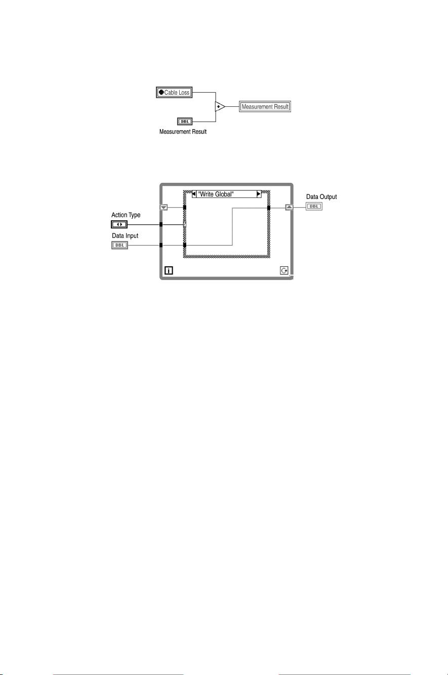
Figure 2.2 demonstrates how a global and local variable can be used on the block
diagram. The global created in Figure 2.1 is used in this VI to retrieve the Cable
Loss parameter. Global variables are easy to distinguish on the block diagram
because of the unique icon that contains the name of the variable. The thicker border
indicates that it is a read variable.
Measurement Result is a control being used in this VI. The result of the addition
is being passed to the local variable of Measurement Result. Local variables can be
created by popping up on a control or indicator terminal and selecting Local Variable
from the Create submenu. Alternatively, drag and drop the local variable from the
Structures palette. Then, pop up on it and use the Select Item submenu to choose
the name of a control or indicator. A local variable can be created for any control
or indicator terminal. As with the global, the local can be used as a read or write
variable and toggled using the pop-up menu. In the example shown, the name of
the local, Measurement Result, appears in the icon. The icon does not have a thick
border, indicating that it is a write variable.
FIGURE 2.1
©2001 CRC Press LLC
The main difference between local and global variables is access. The local
variable is only available on the code diagram it was created on. The global variable
can be used in any VI or subVI. Due to the fact that the global variable is loaded
from a file, any VI has access to this data. While this flexibility seems like a benefit,
the result is a loss of data control. If a specified global variable is placed in a number
of VIs, one of the VIs could be used by another application. This could result in
errant data being written to the global in your main program. With local variables,
you know the only place the data can be modified is from within that VI. Data
problems become easier to trace.
One alternative to a standard global variable is the use of a “Functional Global.”
A functional global is a VI with an uninitialized While loop. The VI can have two
inputs and one output. The first input would be an Action input. The actions for a
simple global would be read and write. The second input would be the data item to
store. The output would be the indicator for the item to read back. The case structure
would have two states. In the Read state, the program would want to read the global
data. The code diagram wires the data from the shift register to the output indicator.
The Write case would wire the input control to the output of the shift register. The
code diagram is shown in Figure 2.3. The benefit of using this type of global is the
prevention of race conditions; an application cannot attempt to write to and read
from the global at the same time. Only one action will be performed at a time.
2.2 CUSTOMIZING CONTROLS
Controls and indicators can be customized, saved, and reused in different VIs. This
allows you to modify the built-in controls and indicators to accommodate your
applications. This section describes the procedure for creating custom controls and
FIGURE 2.2
FIGURE 2.3

©2001 CRC Press LLC
type definitions. A “Type Definition” is a master copy of a control or indicator. When
you need to use the same control in several VIs, you can create a type definition
and save it. Then, when changes are made to the type definition, they will automat-
ically be applied to all of the VIs that use that control.
2.2.1 C
USTOM
C
ONTROLS
To customize any control on your front panel, select the control and choose
Edit
Control
from the Edit pull-down menu. A new window will appear with the control
shown on the panel. This panel has no diagram associated with it and cannot be
executed. Figure 2.4 shows this window with a text ring control on the panel. Also
note that
Control
is the current selection in the drop-down menu on the toolbar. The
control can be modified in either the Edit mode or the Customize mode; the default
is Edit mode when the window first appears. The Edit mode is similar to the Edit
mode of the front panel of any VI where alterations can be made. It allows you to
make some of the basic changes to a control, such as size and color. The Customize
mode lets you make additional changes to specific elements of the control. The top
window in Figure 2.4 shows the Edit mode, and the bottom window shows the
Customize mode. The first button in the window toolbar allows you to toggle between
the two modes of operation.
Each control is a composite of smaller parts. When you modify a control in the
Customize mode, you are then able to modify the parts of the control. If you open
the Parts Window from the Windows menu, you will be able to see the labels for
each part, as well as the position and size of each part. You can scroll through each
part via the increment arrow. One of the benefits of this capability is the ability to
create custom controls. Text or pictures can be copied and pasted into the control
editor. The pictures can become part of the control. This capability makes the creation
of filling tanks, pipes, and other user-friendly controls possible.
Figure 2.5 shows the modified ring control on the front panel. The up and down
scroll arrows were altered for the ring control. Once the desired modifications are
made to a control, you can replace the original control with the modified one without
saving the control. Select
Apply Changes
from the Control Editor window before
closing it to use the modified control. Alternatively, you can save the control for use
in other VIs. Simply give it a name and save it with a .ctl extension or use
Save As
from the File menu. To use it on another VI front panel, choose
Select a Control
from the controls palette and use the file dialog box to locate the control.
2.2.2 T
YPE
D
EFINITIONS
A type definition allows you to set the data type of a control and save it for use in
other VIs. This may be useful if you change the data type and want that change
reflected in several VIs. A type definition allows you to define and control the data
type from one location. It can prove to be very practical when using clusters and
enumerated types. When items need to be added to these controls, you only have to
do it once. Default values cannot be updated from a type definition.


评论4
最新资源